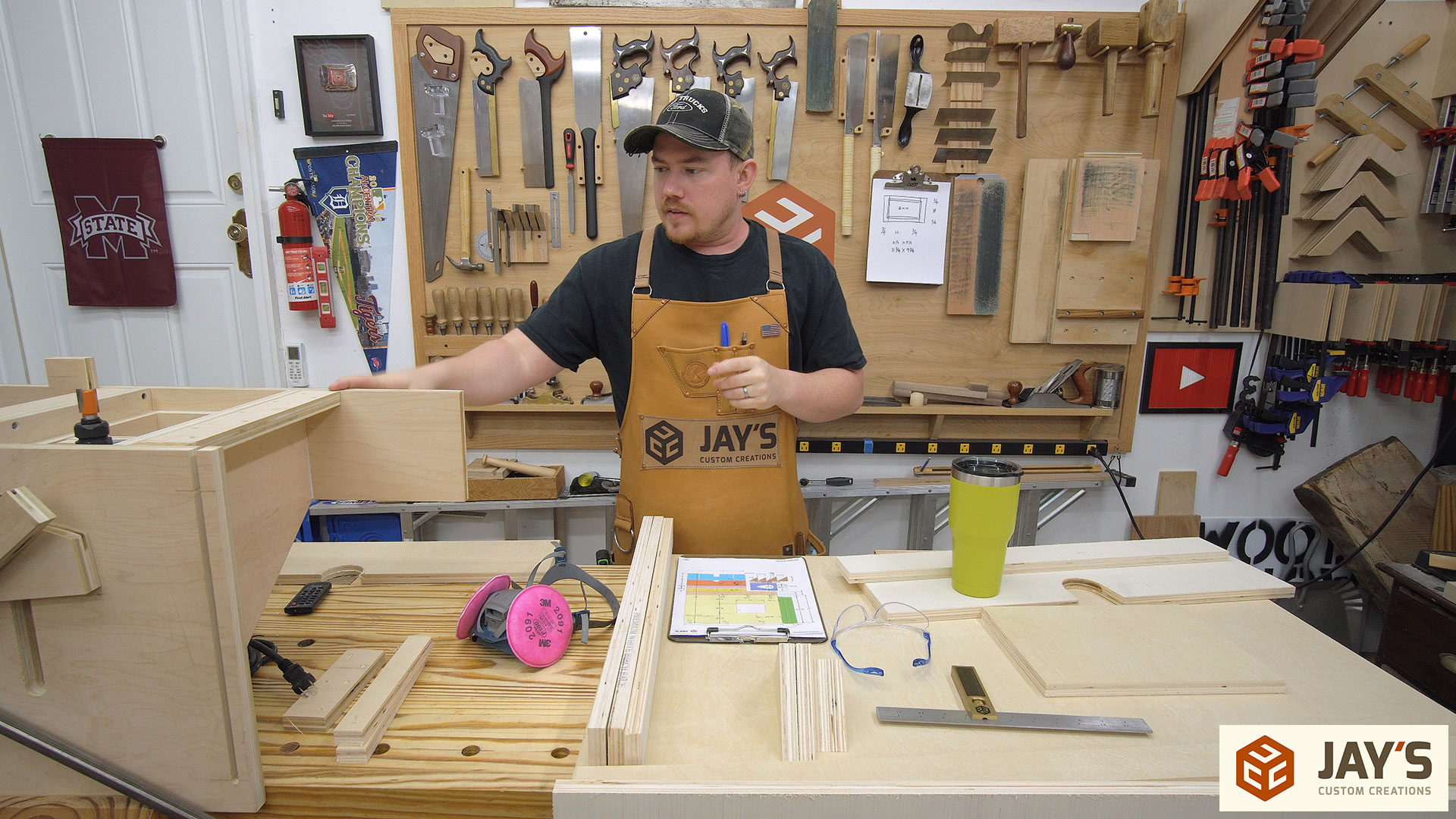
In the last video I completed the prototype for version 2 of my Lever Router Lift. The goal was to create a router lift based upon my last lever concept but slightly larger for a larger router, easier to build, and modify the dust collection so the router would breathe fresh air and the dust collector would never be starved of air. Version 2 turned out just as expected and with no major changes in order I started on the second half of the build; making a new extension wing for my table saw and a router fence to go along with it.
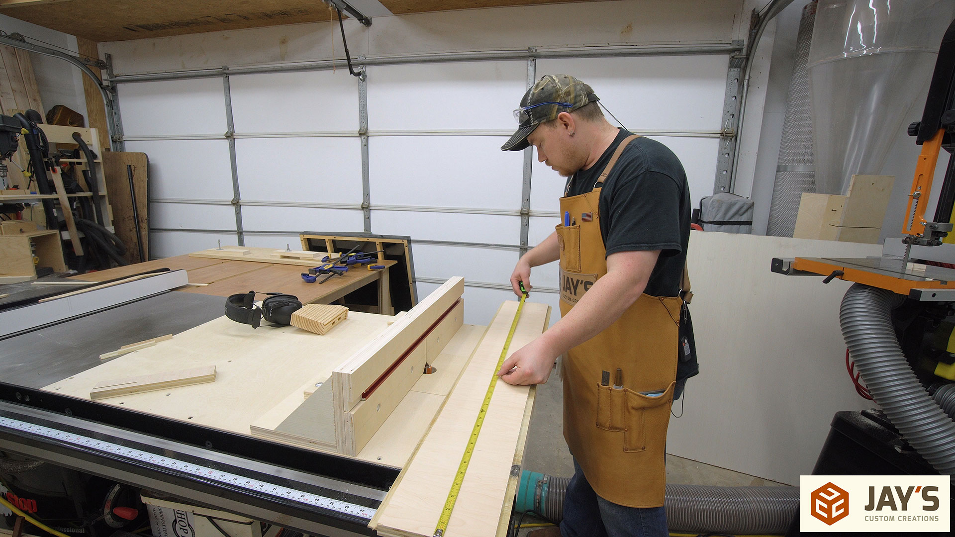
The fence in my first router lift got the job done. That’s about it. The fence faces weren’t easily adjustable. In the new design I wanted to slightly increase functionality by allowing the fences to slide back and forth and lock into place with a wing nut. This type of fence design is very common for router tables.
In the previous video where I built the lift I did very little talking and blew through the build pretty quickly. I knew going into this part that I felt like talking and when I get in those moods the build speed slows down. So to start the wing and fence build I did something I normally don’t do; I cut all of the pieces to size off camera. UPDATE: Plans are completed. If you’re interested in a set of plans click here. I used this router in the new version http://amzn.to/2z7zJaj.
The wing needs to be built first. A simple frame will be the main support for the work surface. Glue, butt joints, and screws are all that is needed. No need for complicated or fancy joinery here.
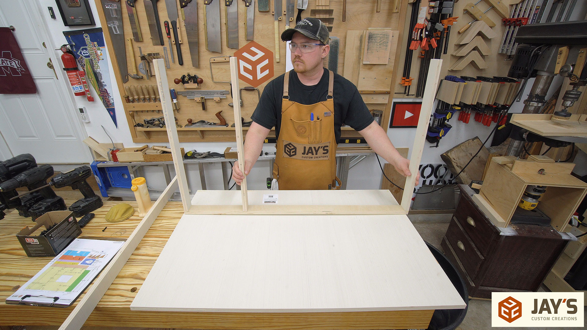
After making the frame the top can be glued to the frame and screwed down from above. I didn’t worry about spacing the screws perfectly or measuring anything off. All the screws were placed by eye. The only thing that is critical is to get the structure below secured so that it is square.

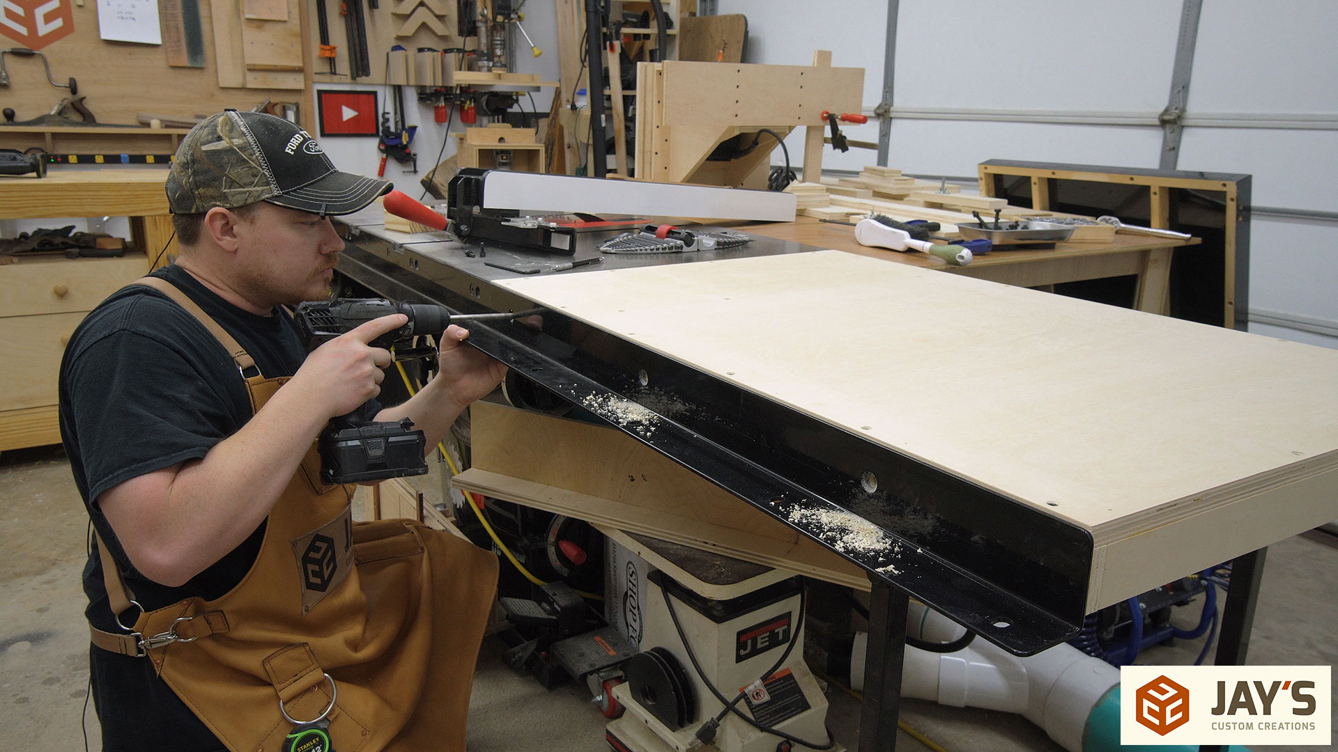
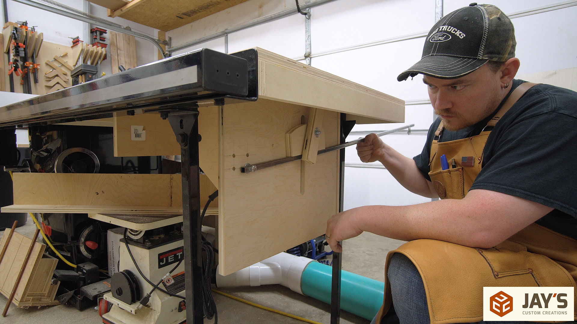
There’s a little bit of back and forth with this build. It’s going to be easier to manage the wing before attaching the lift to it so I went ahead and removed the old wing, clamped the new wing in place with quick clamps, and then drilled the appropriate mounting holes. I also had to jigsaw a couple notches for the wing support that is built into my saw.
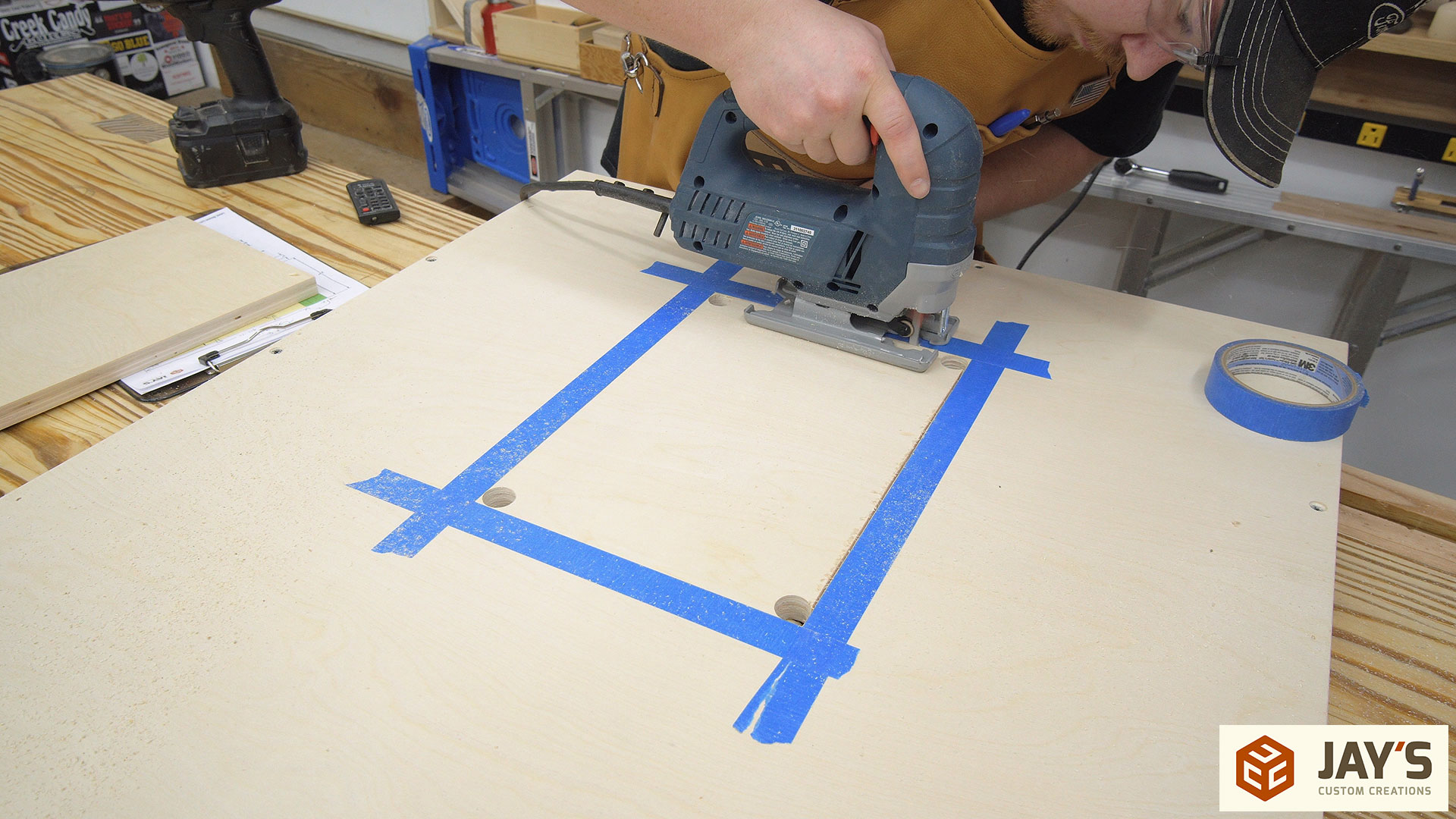
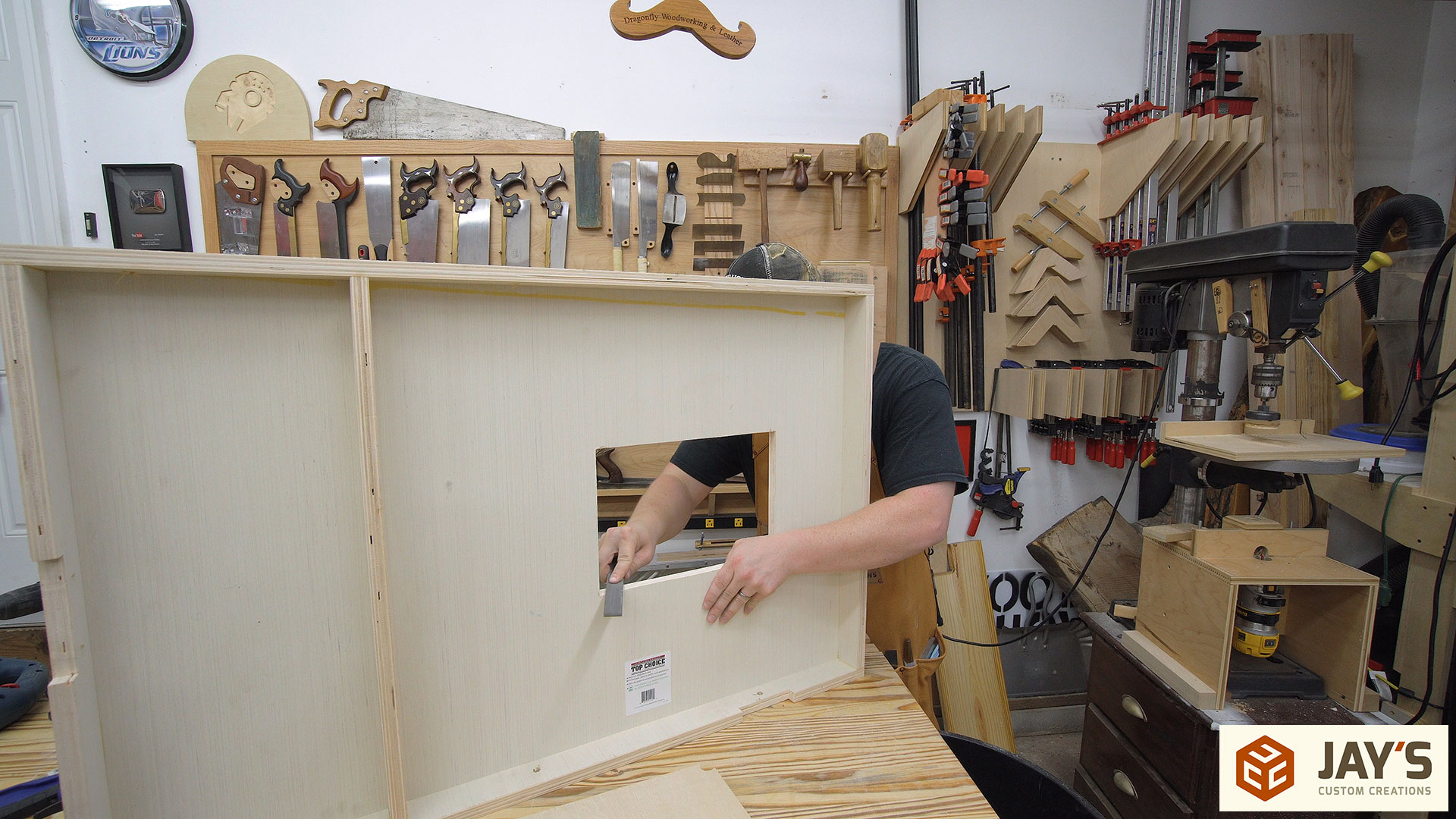
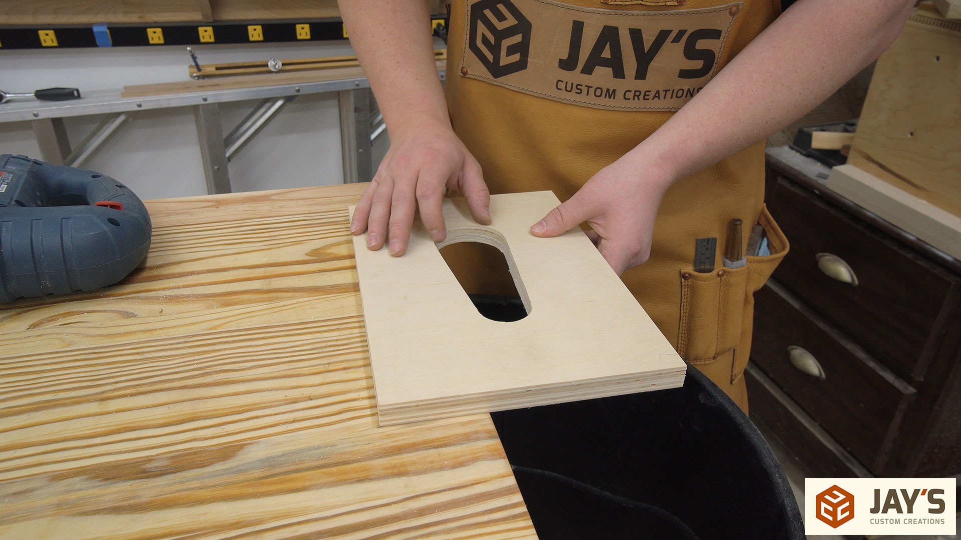
In the last build I used double-sided tape and four pieces of plywood to create a template around the insert plate. Then the inside was removed with a jigsaw and the exact shape was created with a trim router and a flush trim bit against the template. To show another way to get good results I traced the insert plate with a pencil, added tape to the surface to prevent tearout, and cut to the line with my jigsaw. I will admit that having a decent jigsaw makes all the difference in the world in cut quality. If a decent result is desired I won’t be using my cordless Ryobi jigsaw and will always reach for my corded Bosch jigsaw. It’s just one of those tools where there is a significant performance difference in the lower end tool vs a more expensive one.
Although the cut was a good quality cut I still needed to refine the size a bit. I chose to remove more material around the insert plate opening with a file rather than reduce the size of the insert plate with a plane. That way if I need to make another insert plate in the future I will be closer to the whole number I started with for the insert plate dimensions.
With the wing already put in place to locate the mounting holes and the insert plate opening already cut we (both of me) can finally secure the lift to the bottom of the wing.
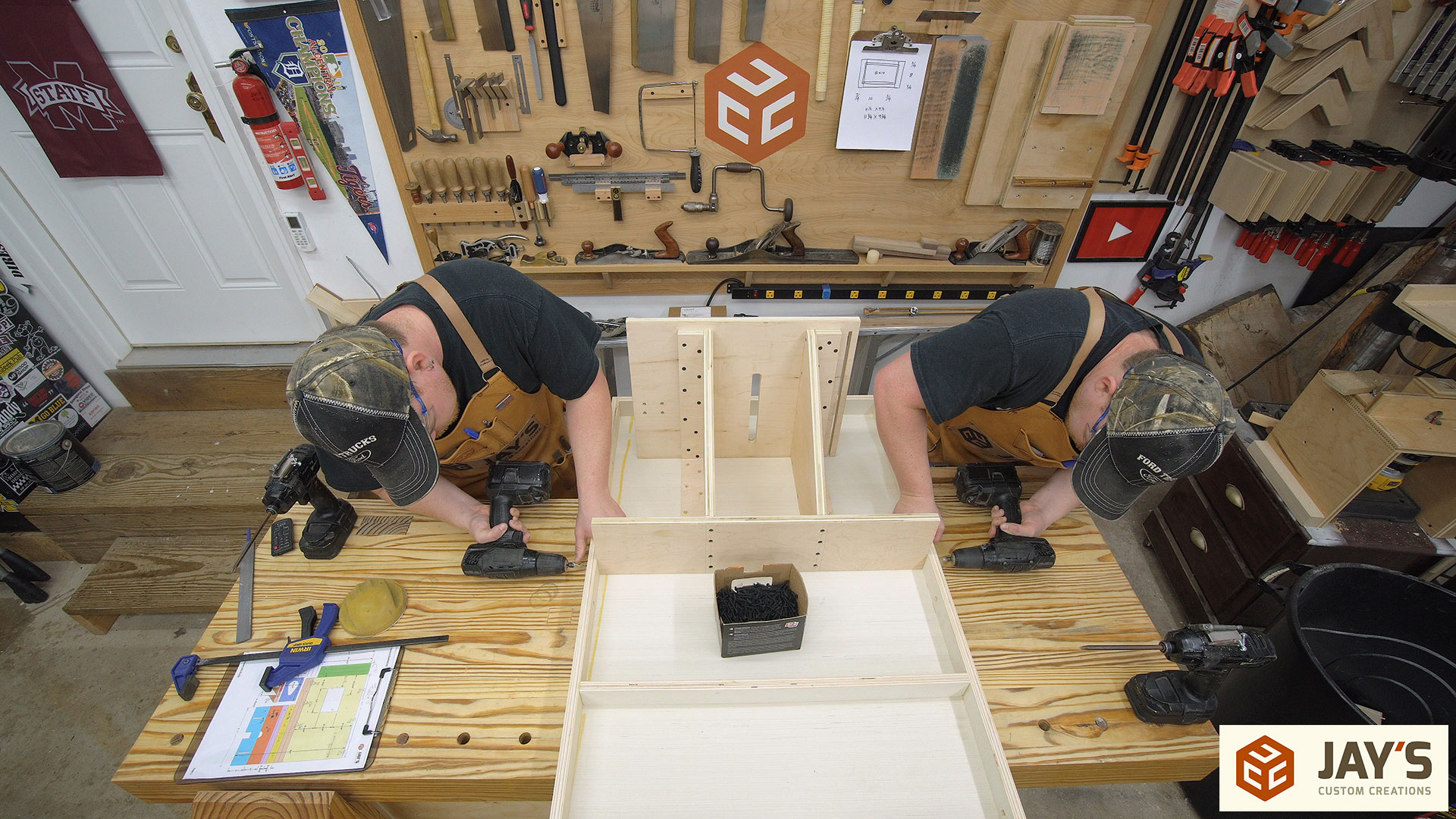
Installing the wing will be unique to the saw you have so I won’t cover the specific nuts and bolts there. After getting it installed I can do the final modification to the router carriage. The dust collection plate is removed, a 4” hole cut for the dust collection, and a 4” dust collection port is added.

The router carriage is made to be inserted from below. The main bolt coming through the front will prevent it from falling to the floor in the even that the handle is accidentally dropped with the locking knob backed off.
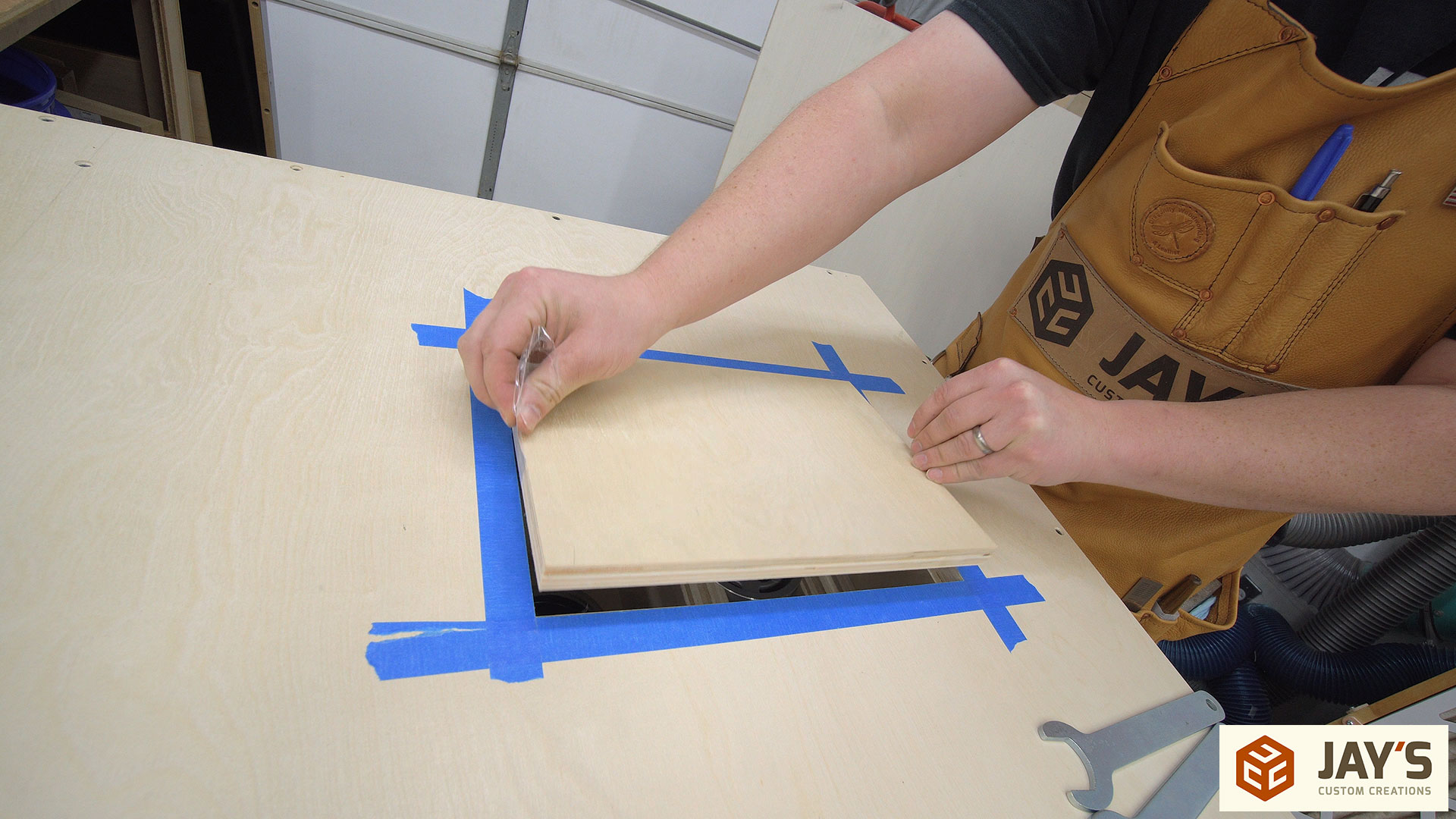
To locate the center of the router bit I installed a 3/8” spiral upcut bit in the router and positioned it to cut about 1/8” into the bottom of the insert plate. Then, with clear packing tape on each end of the insert plate to act as a handle, I lowered the insert plate onto the spinning bit to make a shallow cut. The insert plate is sized so that it can be rotated 180 degrees and have a different size opening.
At the drill press I used a 3/8” forstner bit and lowered it into the routed holes to locate the center. Then, without moving the insert plate, I switched to the appropriate size drill bit to cut each of the holes.

And connected the holes to form a tapered slot. The shorter side can be used with smaller size router bits and the wider side can be used with wider sized router bits. I always have the option to make other insert plate sizes as well. PRO TIP: Put a trash can right next to your workbench to sweep debris right into it or cut over it in situations like this. Doing this requires less effort than sweeping the floor and picking up larger piles more frequently. :)
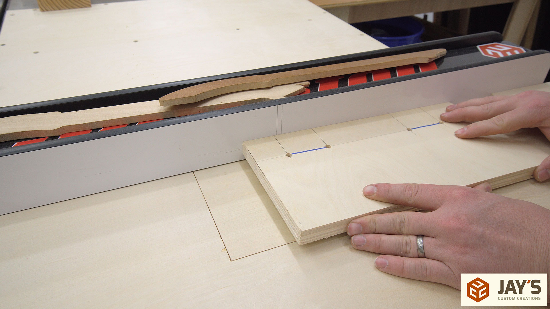
At this pint the router lift and table could be used….so that’s exactly what I did. I needed to cut slots for the front movable faces so I set a spiral up-cut bit to remove slightly more than half of the material thickness and cut from both sides. It’s worth noting that before doing this I transferred the location of the front and back of the router bit to the fence and also extended my slot lines on the material. This allows me to know what is being cut without actually seeing the bit.
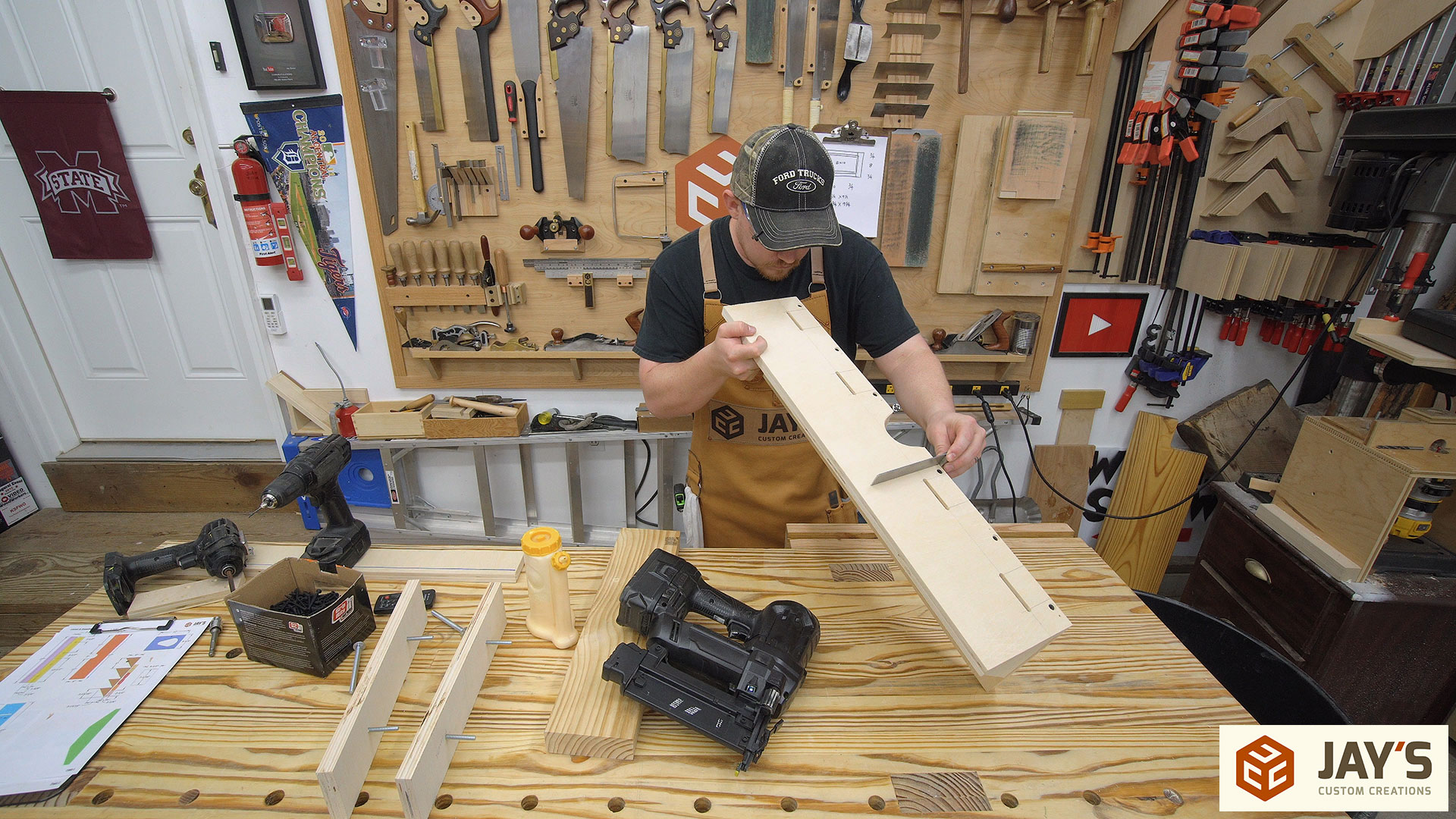
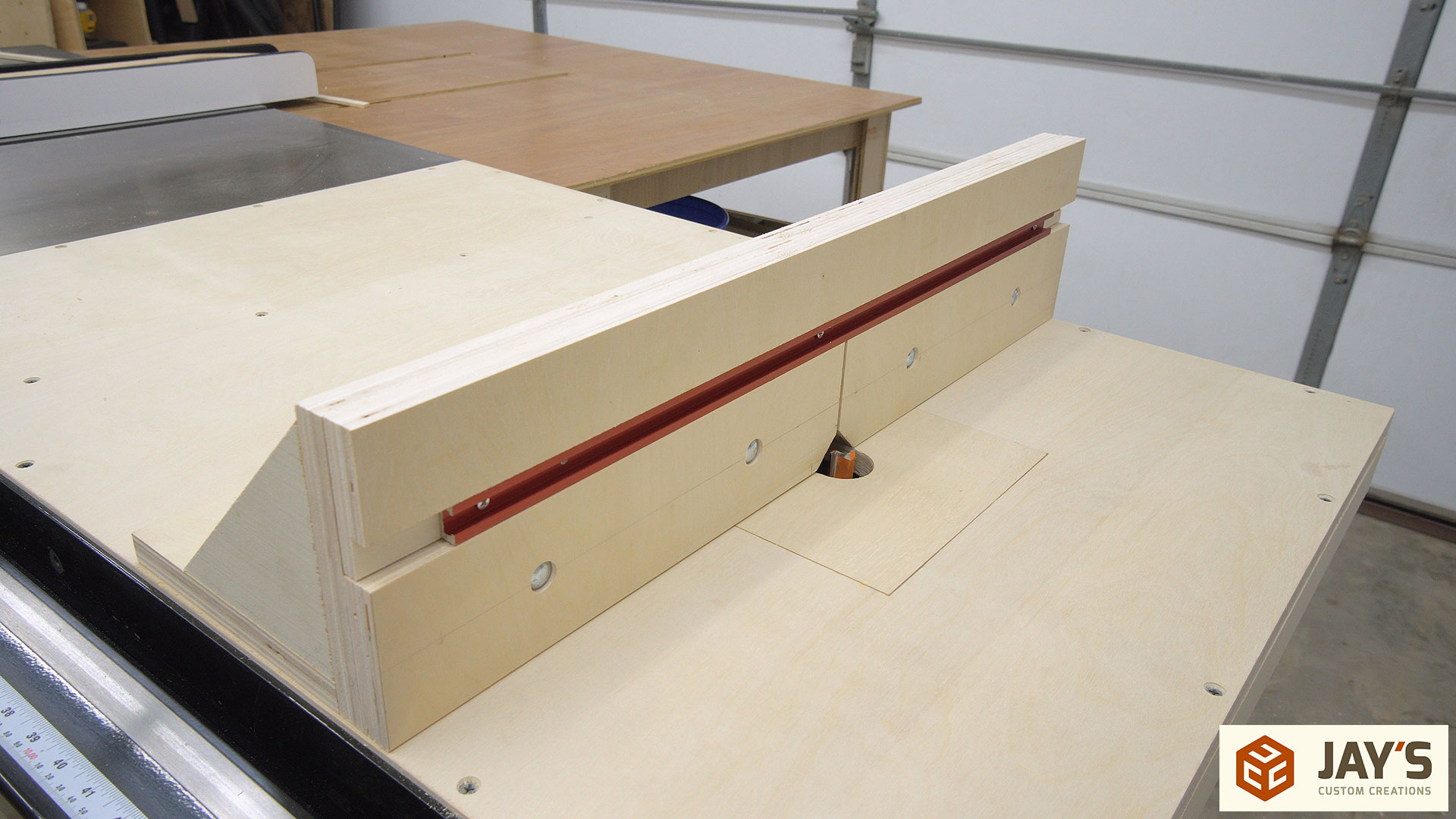
After the fence pieces are finalized the assembly can start. The slotted front piece is attached to the base with glue and screws and the four triangle braces are added to the back with glue and brad nails. It’s important to make sure you constantly check the bottom to front angle for square. Make any adjustments needed as you go. If everything is square then the final angled piece to box off the dust collection area can be installed as well.
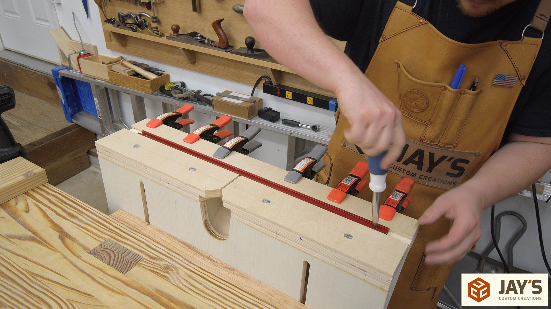
If t-track is going to be used above the sliding faces a rabbet or dado is needed in the fence’s upper fixed piece. I made a rabbet with two cuts at the table saw and glued the piece in place with a few spring clamps. My t-track wasn’t as long as it needed to be visually but as far as it will be used it’s plenty long enough. That can be screwed into place while the glue sets up on the fixed piece.
With the fence pulled forward about as far as I think I’ll ever need it I drilled a hole in each of the fence base slots for hold down knobs. These knobs crab onto a t-nut seated into the table from below.
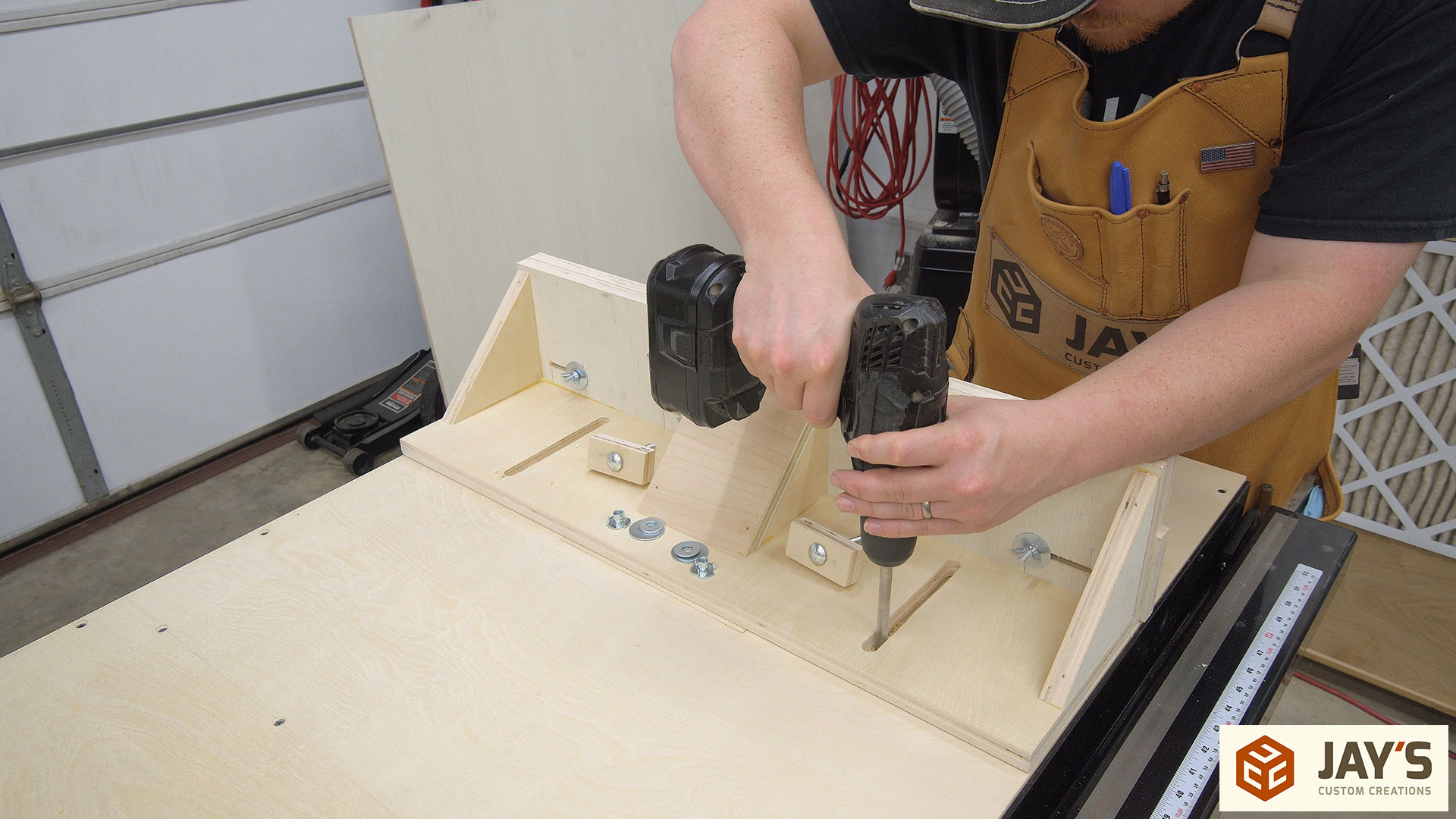
The knobs are just a rectangular piece of plywood with a carriage bolt through the middle. The fence should be easy to slide forward and backward and held in place securely with the two knobs.

Changing the bit is easy with the assistance of any of the interior faces of the lift. Just position the lower collet wrench against any of the internal faces and use both hands on the upper collet wrench and the router bit.

In both the first design video as well as the version 2 video I received a lot of comments along the lines of “How do you micro adjust it?” Easily, with your hand. Simply grab the side of the front plate and rotate your hand up or down as necessary and you can really dial in the exact height needed.

It works great….and I’m excited to use it going forward. :)

The dust collection is fantastic. No complaints at all there. It was really rewarding to see four 41” long rabbets being cut and the only dust I could see being made was when the router bit blew out the back side of the material.
To close I’ll say that I’m extremely glad I finally got off my butt and got this build completed. I’ve been wanting to make a stand alone router table for a couple of years now and simply never got around to doing so. Nothing but excuses. Incorporating it into my table saw extension wing just like last time will give me the same features I’d expect in a router table while eliminating the need for dedicated floor space. UPDATE: Plans are completed. If you’re interested in a set of plans click here. I used this router in the new version http://amzn.to/2z7zJaj.


I just noticed that you have a Starkville address! I knew there was something great about the ideas and plans I get from you. I am an MSU alumnus and live in Brandon, MS.
Keep up the good work.
Good stuff Jay. I have a small space to work in, so I can see adding a router wing in my future. Quick question: what is your preferred screw in these types of shop projects with plywood: wood screw, drywall screw, etc?
For non furniture stuff a regular coarse thread drywall screw is fine.
Hey Jay, great stuff, I have a small shop a I appreciate the stuff I get from you.
Keep up the great work.
Jay Nice home made router lift.
I have 2 Dewalt 625 plunge router.s
Would there be some way your lift could be changed to allow my Router to fit.
Jeff
This one is designed to incorporate a cylindrical router. Any changes to the mount would be based upon your specific router.
Jay, I like the project and I see that I might do something similar in the future instead of a dedicated router table. I have a limited amount of space.
Why did you choose to use the bolts down through the worksurface to adjust the router fence and not some how attach the router fence to the side of the tablesaw fence and use that as your lateral adjustment?
You do great work with both your project and your videos.
So I can use the router and leave my table saw setup for a cut.
Good point, never thought of that
between the router lift and the saw wing, how many sheets of plywood did you need?