When getting a new CNC machine there are two things I recommend doing. The first is to use the CNC to flatten the spoil board or waste board. This will ensure proper cutting depth results on future cuts. The second is to use the CNC to engrave a grid into the waste board.
Cutting a grid into the waste board is optional but I still recommend doing it. By doing so you are giving yourself an exact visual representation of the limits of the machine as well as reference lines that are exactly in line with the X and Y travel directions of the machine. This helps in lining up smaller material at various positions on the waste board.
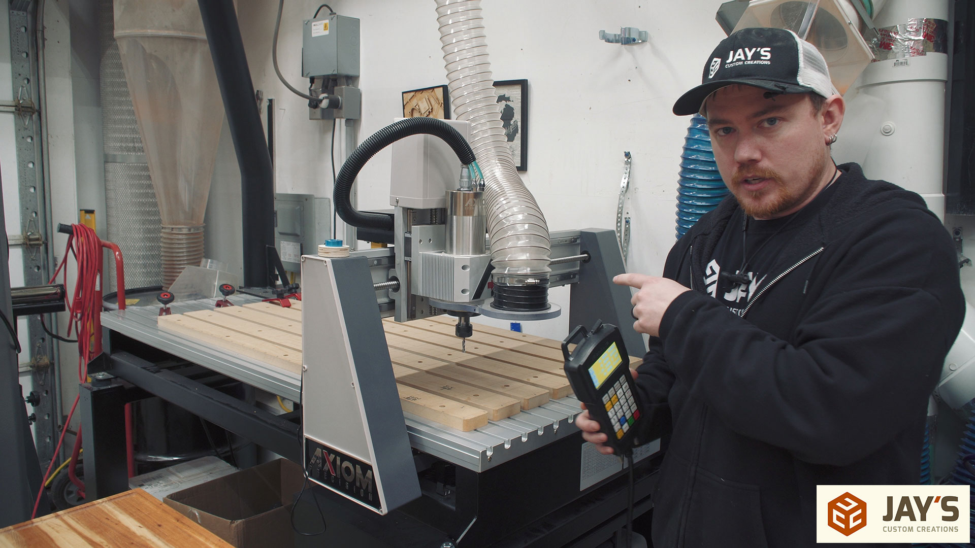
The first step in engraving a grid is to establish the maximum values for X and Y travel. My machine is an Axiom AR8 Pro+ and it is controlled with a RichAuto controller. If you have a different machine this process might be different. To start, the machine is moved to the Home position. The Home position is different from the cutting file origin or the current origin set in the controller. The Home position is the absolute 0,0 value for X and Y. For this machine 0,0 is set to the front left corner. When homing the machine via the controller the machine knows where to stop due to the placement of limit switches on each axis. These limit switches tell the machine when to stop and let the machine know its exact position, or Home. In the following image the machine is not at the Home position.
Pressing the Home button followed by the OK button will move the machine to the Home position. First, the spindle rises to the top of the Z axis until the limit switch is activated. Then the spindle is moved to the left until the X axis limit switch is activated and the entire gantry moves forward until the Y axis limit switch is activated. Once all three limit switches are activated the machine knows the exact location of the spindle and uses it as a reference point for all future moves and origin adjustments until the machine is powered down. Homing the machine is necessary every time the machine is turned on to let the machine know it’s position.
The CNC I’m using has up to 9 programmable origins. This allows you to set an origin to a commonly used location as a starting point. It’s extremely handy for various different situations. One example would be if you are batching out a lot of items that take up less than half the cutting area. One origin can be set to the back half and one set to the front half. The machine can be cutting material on the back half while you work on getting the front half ready for the next cut. When the back half stops you can change the origin to the front half, start the new cut, and work on removing and replacing the material on the back half and then repeat the process over and over to reduce downtime of the machine.
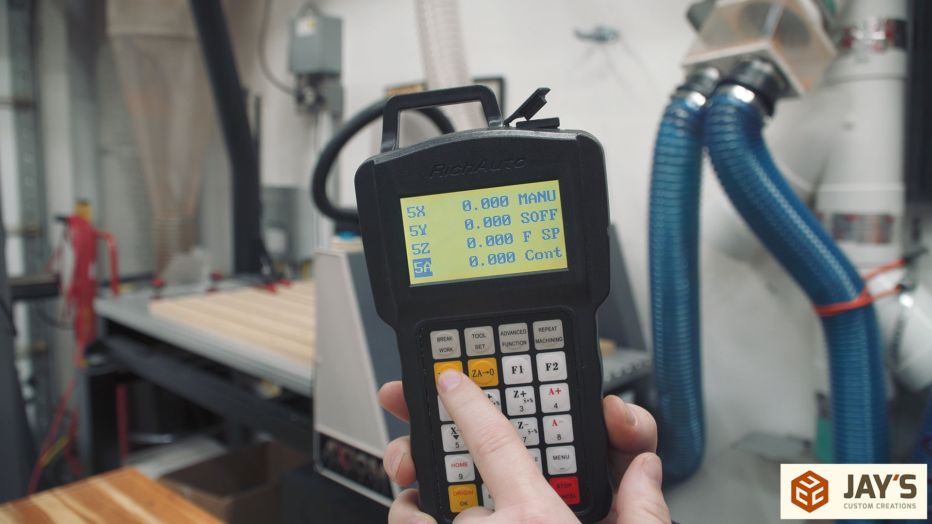
With all of that said, I set the machine to origin #5 as I’m currently not using it. It will be fine for this test. Then with the machine still at the Home position I pressed XY->0 on the controller to clear any set values and reset the current origin to 0,0.
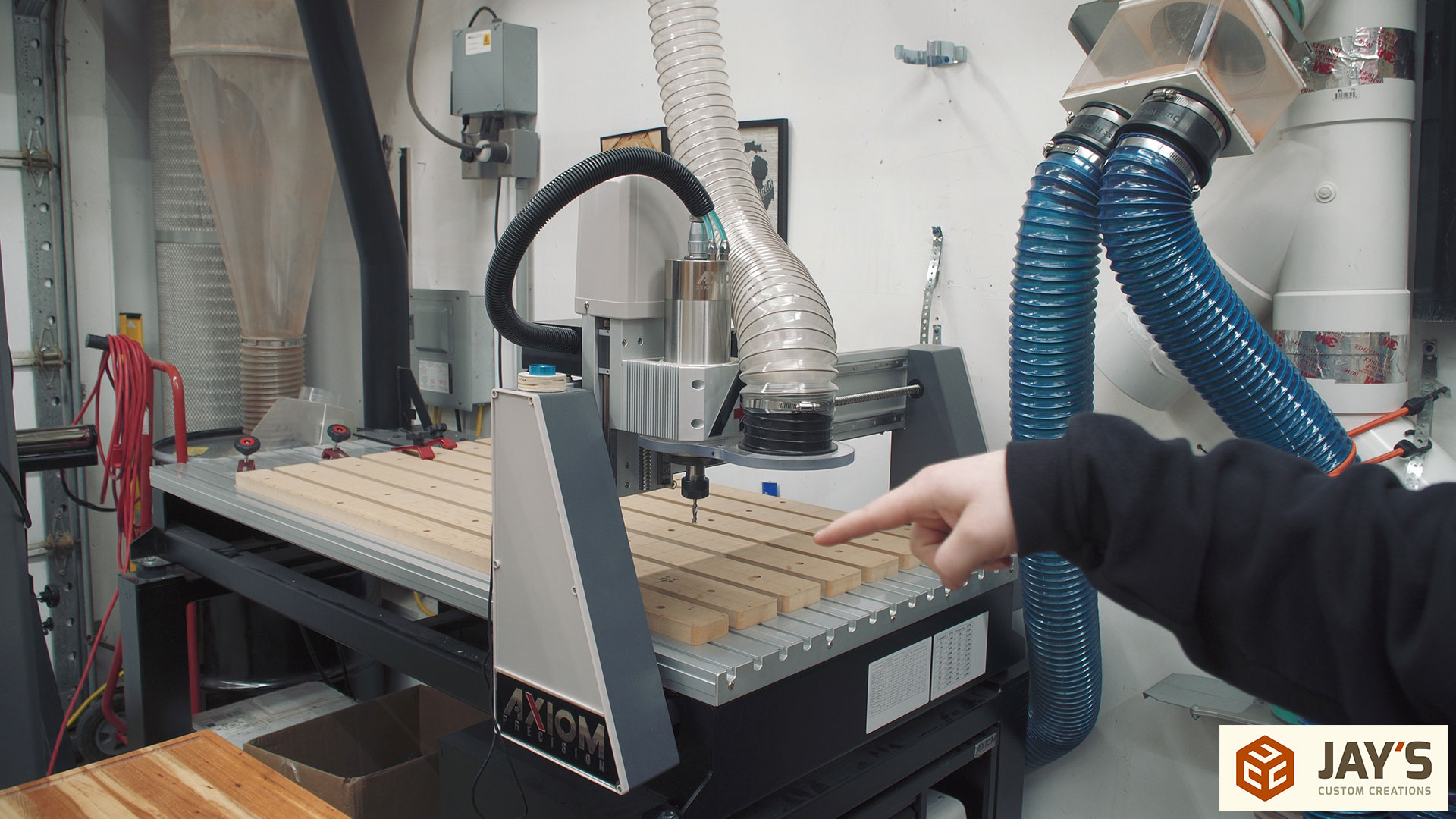
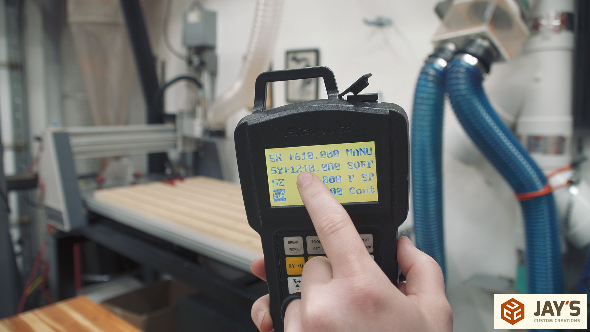
Now the maximum values can be determined. This process might be different for your machine but all we need to determine is the maximum values. In my case, the machine has a maximum value for X and Y in the machine. I could go into the settings to see what was programmed but manually moving the spindle and gantry will allow me to confirm those numbers. With X+ and Y+ held down on the controller the machine will reach the maximum values and stop in each direction.
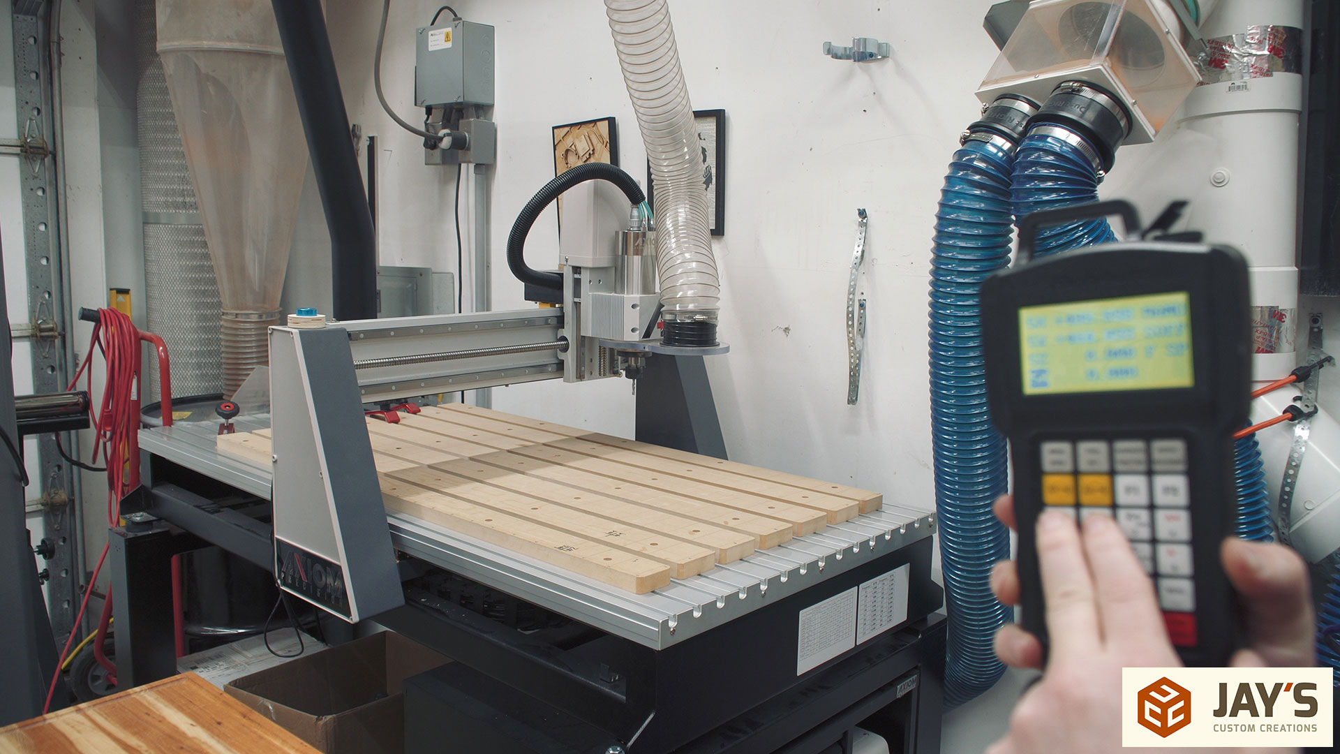
On the controller the maximum values are displayed and confirmed with what was programmed. In this case the maximum value for X is 610mm and the maximum value for Y is 1210mm. The machine is set up with metric units but the software allows for either metric or imperial units to be used when in the CAD/CAM process. Now that we have the EXACT cutting area of the machine we can go to the computer to create a cutting file.
This is where I’ll refer you to watching the video. I showed two different methods to get a cutting grid and showed why one is slower than the other. In a 2d view each grid looks the same but when a cutting path is made the cut time can be much different. Open vectors is the reason why the cutting time is different.
When an open vector is cut the spindle plunges at the beginning of the vector, travels along the vector, and is then lifted up at the end of the vector. The machine then makes a rapid movement to the start of the next vector and the process is repeated for every open vector. Rapid movements are generally programmed to be much faster than cutting movements but because no cutting is being done in a rapid movement you aren’t making any progress on the cut. It’s simply wasted time. Therefore, reducing or eliminating rapid movements will decrease your overall job time and increase productivity.
In this example you can see the 2” x 2” grid in blue. Each one of those grid lines is a unique open vector. Just regular straight lines vertical and horizontal that are all independent of one another. All of the red lines are rapid movement lines. Again, this is time wasted where the machine picks up and moves to the next cut. This set of 38 open vectors is a good example of an inefficient CAM toolpath.
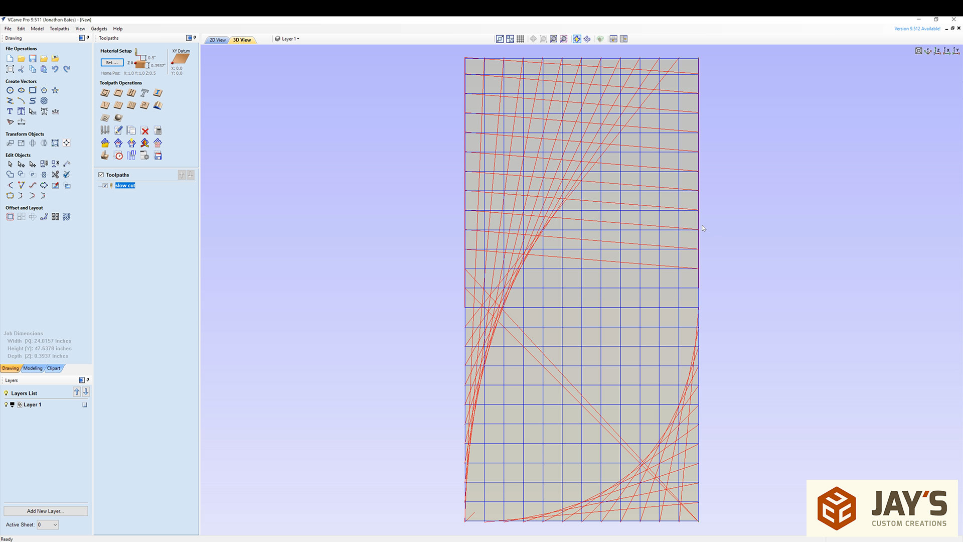
In this next image you can see the same 2” x 2” grid in blue but this time it was created differently. Instead of 38 open vectors it is reduced to two open vectors. And technically they could have been joined to create just a single closed vector. Notice the single red line, meaning only one rapid movement for the entire cut.
In the previous example all of the open vectors were single horizontal or vertical lines. In this example the open vectors were created with multiple lines joined to one another. The lines in the previous example could not be joined to create larger open vectors because in order to do so the endpoints of the vectors need to touch. Joining the last set of open vectors would result in a single rectangle around the perimeter and no change to the lines in the area. Again, it’s better described in the video.

With the cutting speeds the same you are going to really save time by reducing or eliminating rapid movements of the machine. The slower the rapid movement speed of your machine is set to the increased amount of time it will take to cut the inefficient toolpath file. The faster the rapid movement speed is set in your machine the less of a difference you will see when cutting a lot of open vectors.
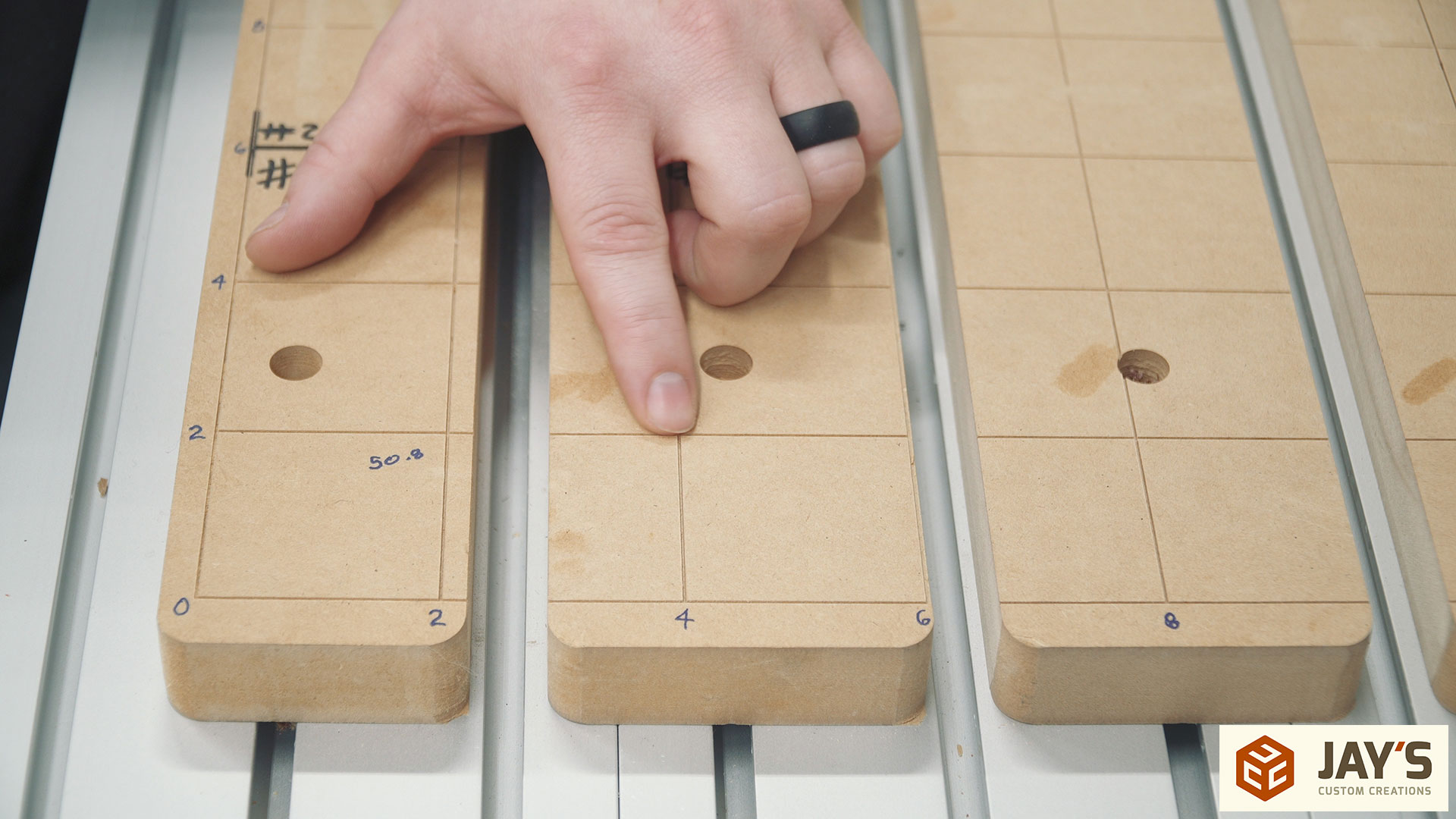
It’s been a little while since I cut the grid into my waste board and it’s been a treat to have. It’s extremely easy to line up smaller material to the X and Y axis regardless of where it is on the machine and I can easily place items in a repeatable location without the use of stop blocks if needed.
I don’t recall the exact cutting depth of my grid but I think it was around .005”. I used a Whiteside SC70 30 degree pencil point engraving bit and I believe I kept the same feeds and speeds as indicated in VCarve Pro.


Jay was watching you video on your waste board set up .
I also run vcarve pro. 9.511
Have a question about your screen in vcarve.
How did you get the design and toolbar both on the left side of your design area.
Thanks Jeff
See this video: https://www.youtube.com/watch?v=03UzQ-e8wKo
Great Video Jay! I learned a lot from this some day I would like to get a CNC machine