Previously, I made a MATCHFIT Work Horse. It combines the workholding capability of a workbench with the portability and form factor of a saw horse. In this video and article, I’ll show you how I made another Work Horse but this time focused on traditional workholding options. Before I begin, here are a few helpful links pertaining to the build:
– Plans for this Work Horse (included with the MatchFit version): https://jayscustomcreations.com/product/matchfit-work-horse-plan/
– Vertical bench clamps: https://lddy.no/12169
– Inline adjustable bench dog: https://lddy.no/1216b
– Twin screw vise kit: https://lddy.no/1216e
– Steel knobs in ¼-20: https://lddy.no/1216f
– Brass bench dogs: https://lddy.no/vlkb
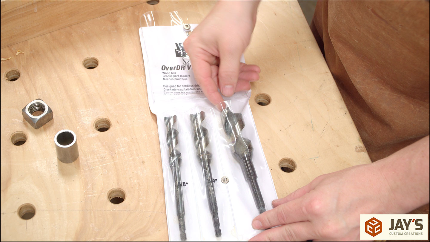
– Overdrive drill bits: https://lddy.no/1216i
– Cork rubber vise lining: https://lddy.no/ylyi
– Push toggle clamp: https://lddy.no/1216k
– Steel guide bushings: https://lddy.no/1225t
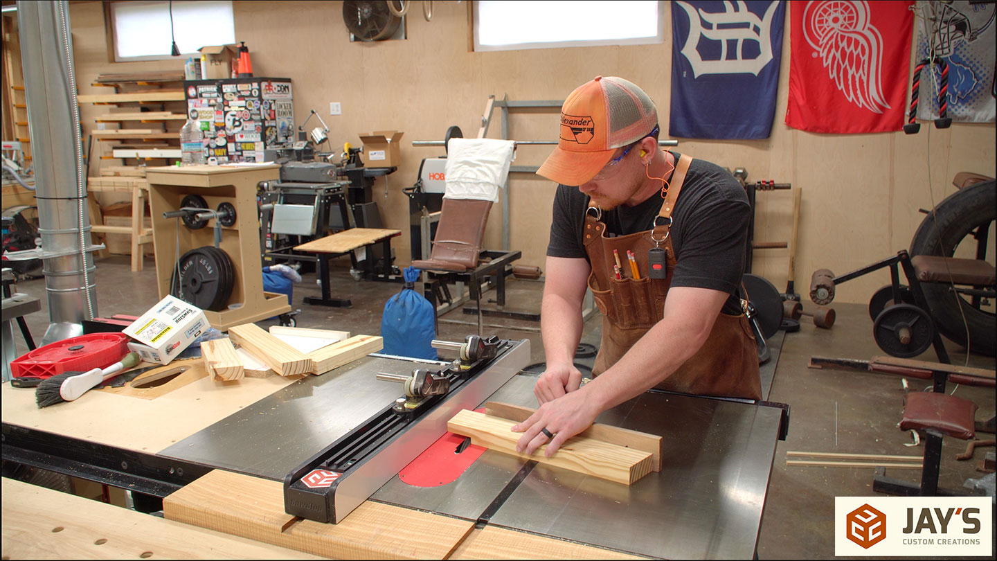
As I begin this project allow me to tell you a little secret. You see here that I’m using a workbench to build a workbench. It’s kinda like “what came first? The chicken or the egg?” The truth is, if you think you need a workbench to build a workbench then you are correct. If you think you do not need a workbench to build a workbench then you are correct. As Henry Ford once said, whether you think you can or you think you can’t, you’re right.
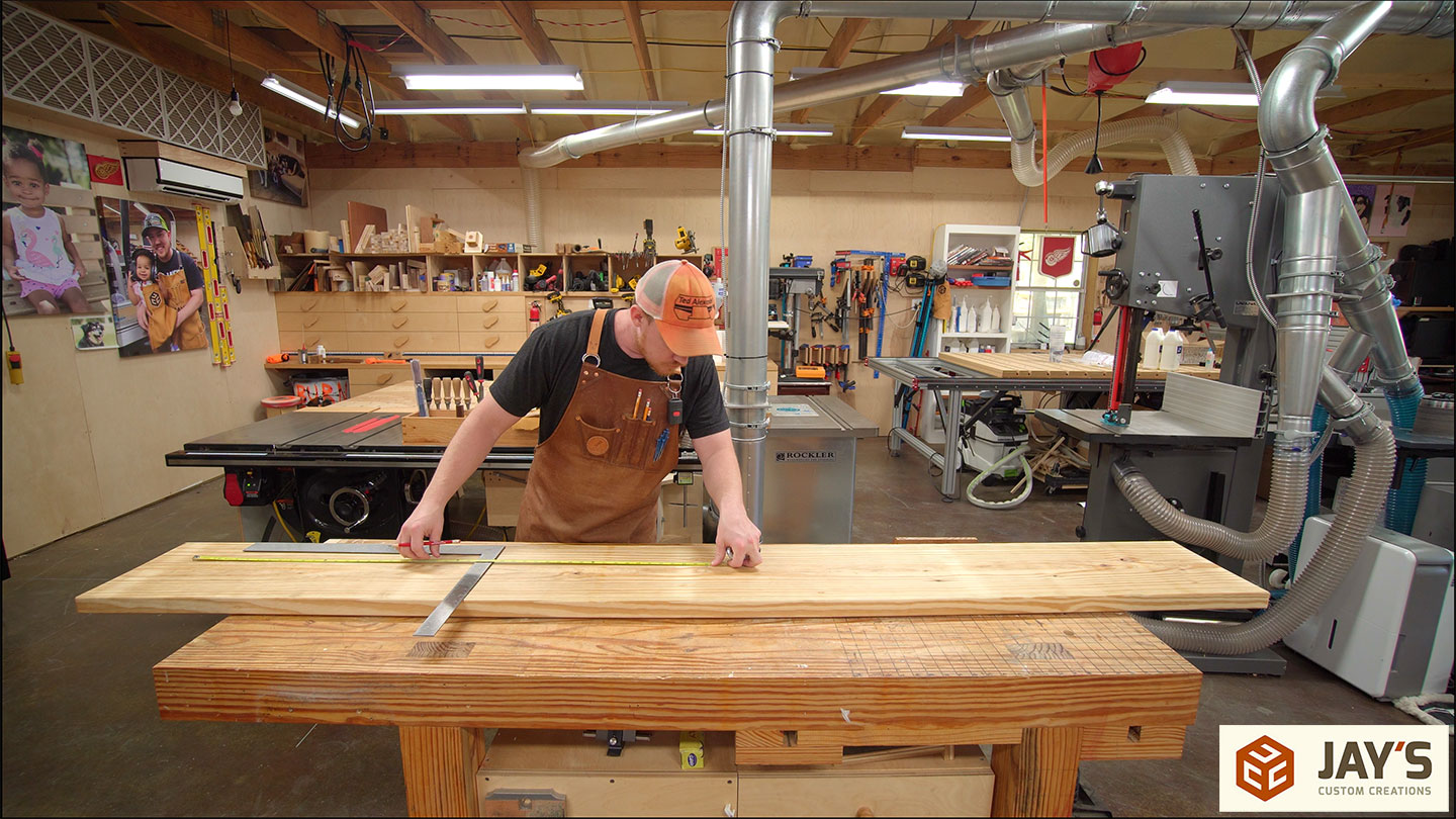
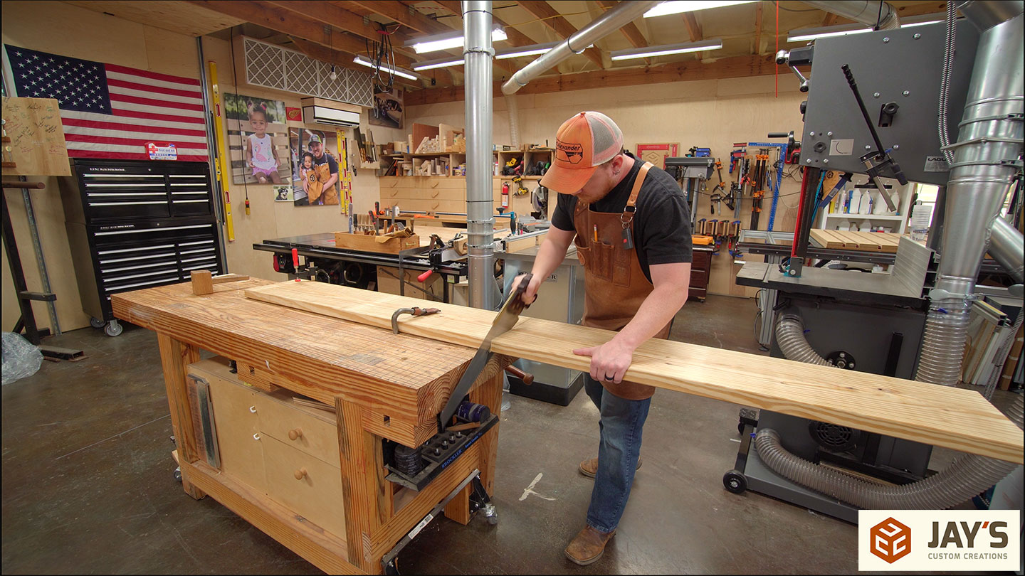
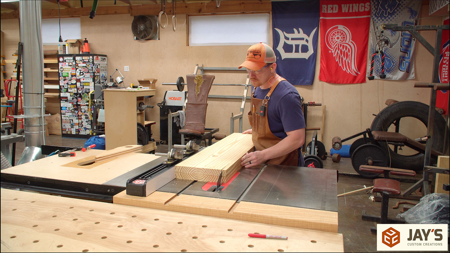
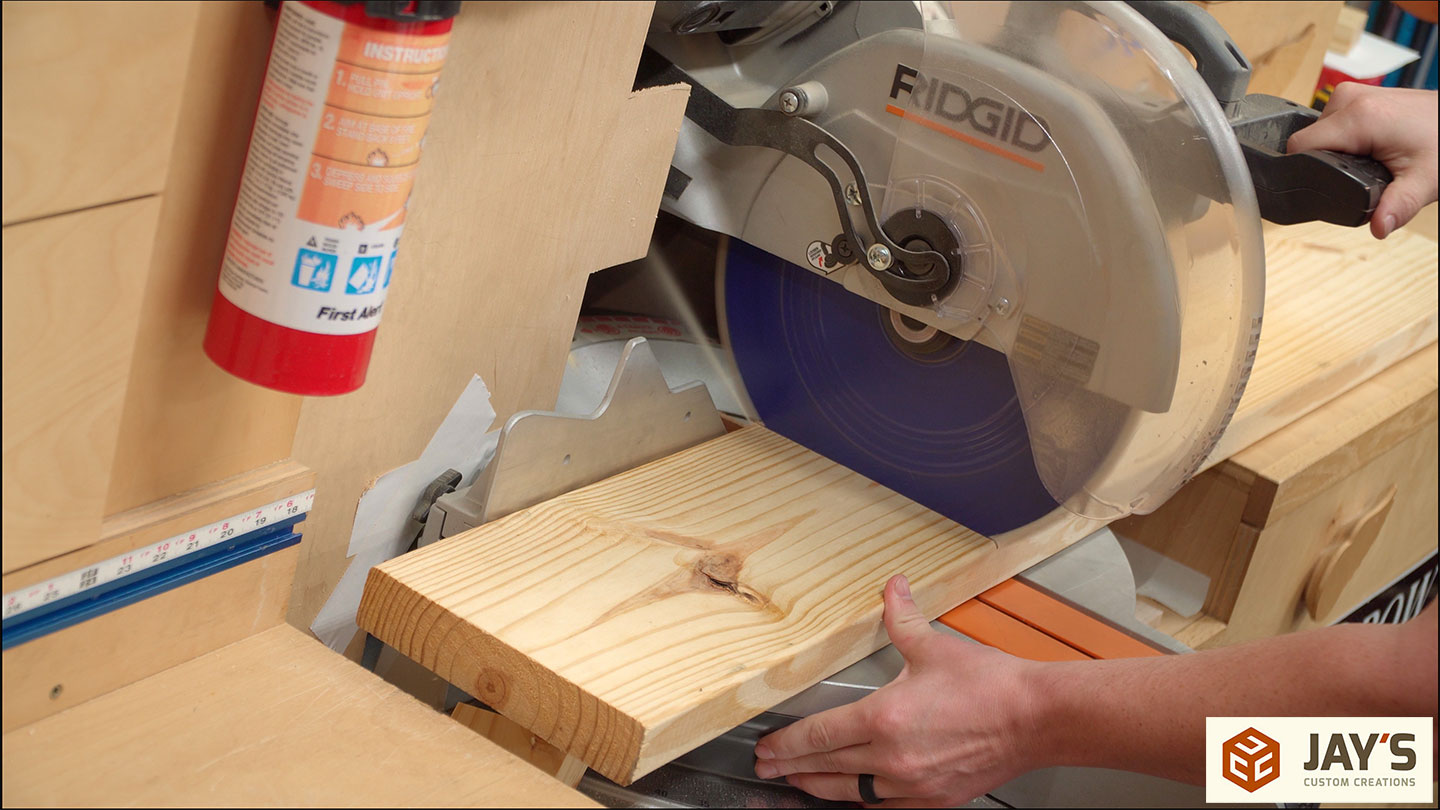
The first step in this build is to crosscut a 2×12 southern yellow pine board for the two pieces that will make up the top. The saw I’m using here is a 0.37 HP BearKat with an off-grid calorie-burning power plant. The one board is cut into two bards plus firewood.

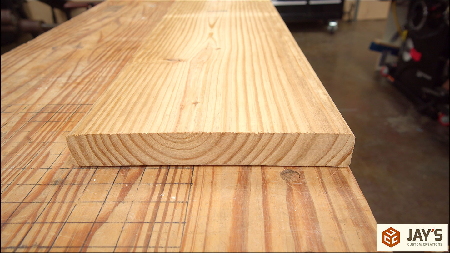
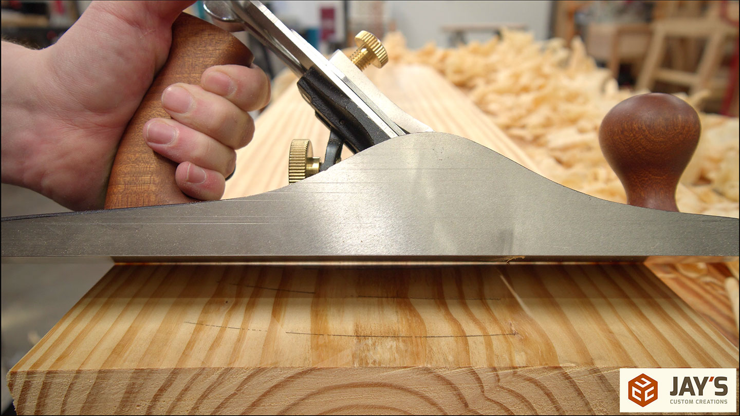
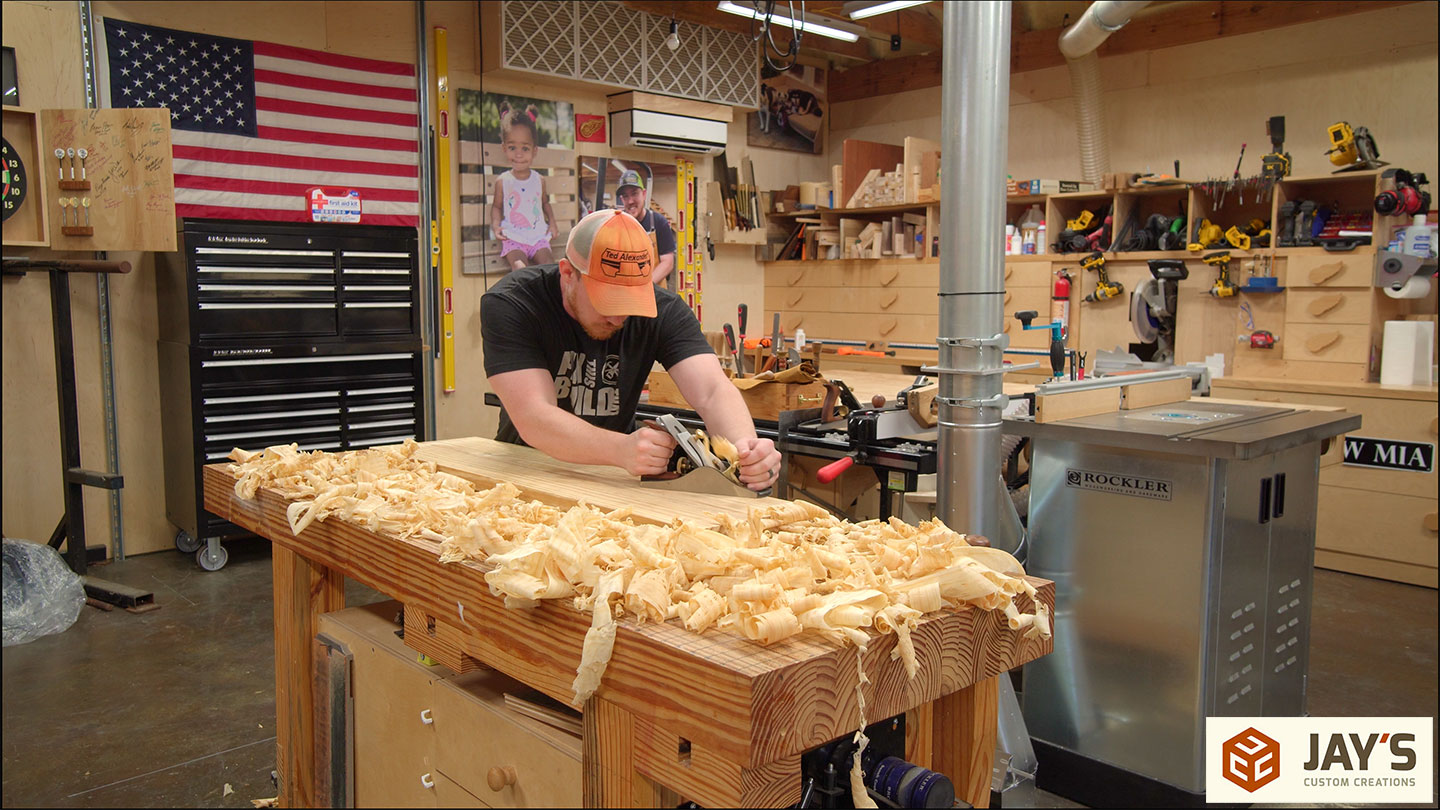
Here you can see the amount of cup that needs to be removed before I can glue these together.
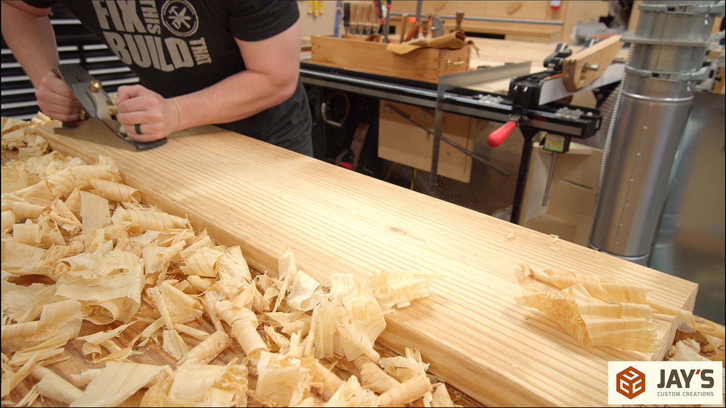
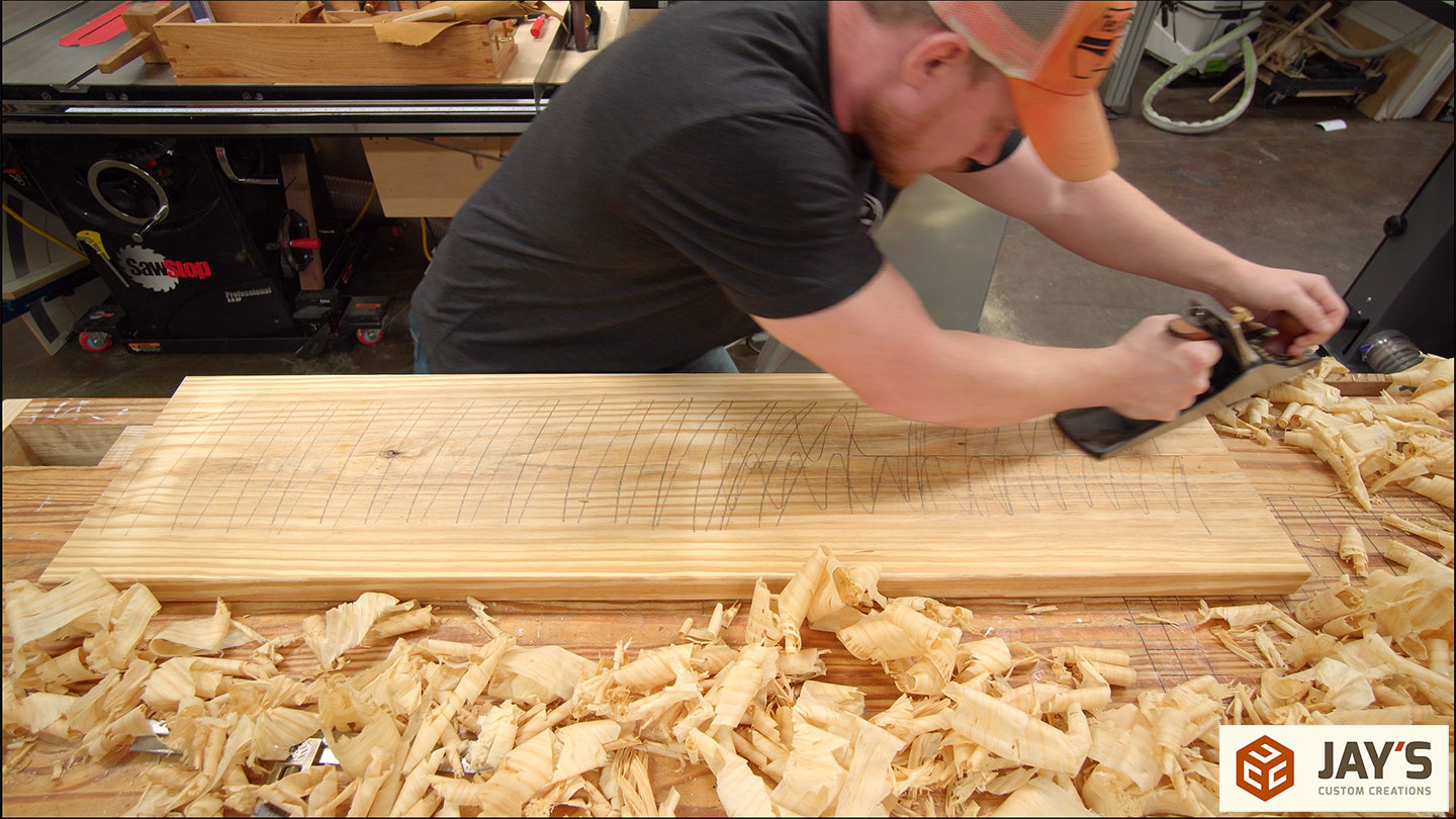
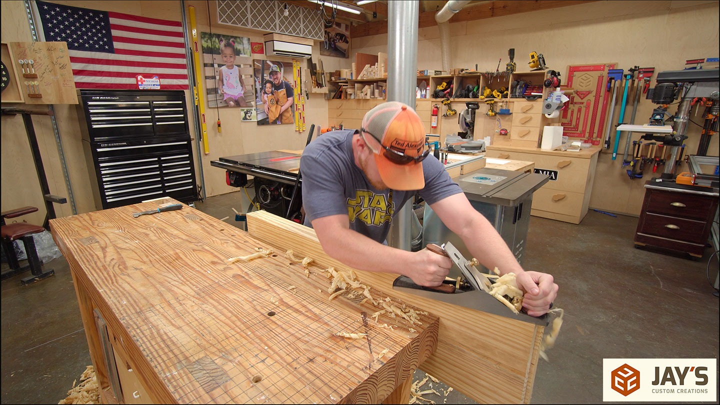
The weapon of choice is a 6.9 pound iron paperweight that also conveniently shaves wood quite well. In all seriousness, this is a TayTools 5-1/2 Jack Smoothing plane that is arguably the best bang for your buck in the hand plane market. With an aggressive set, the board is traversed in various directions to remove the high spots.
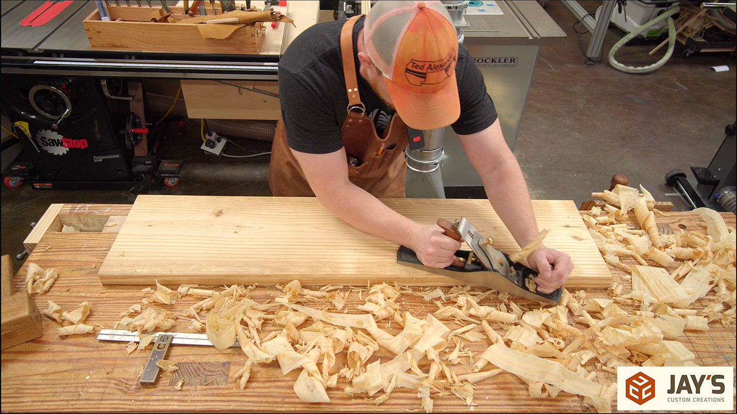
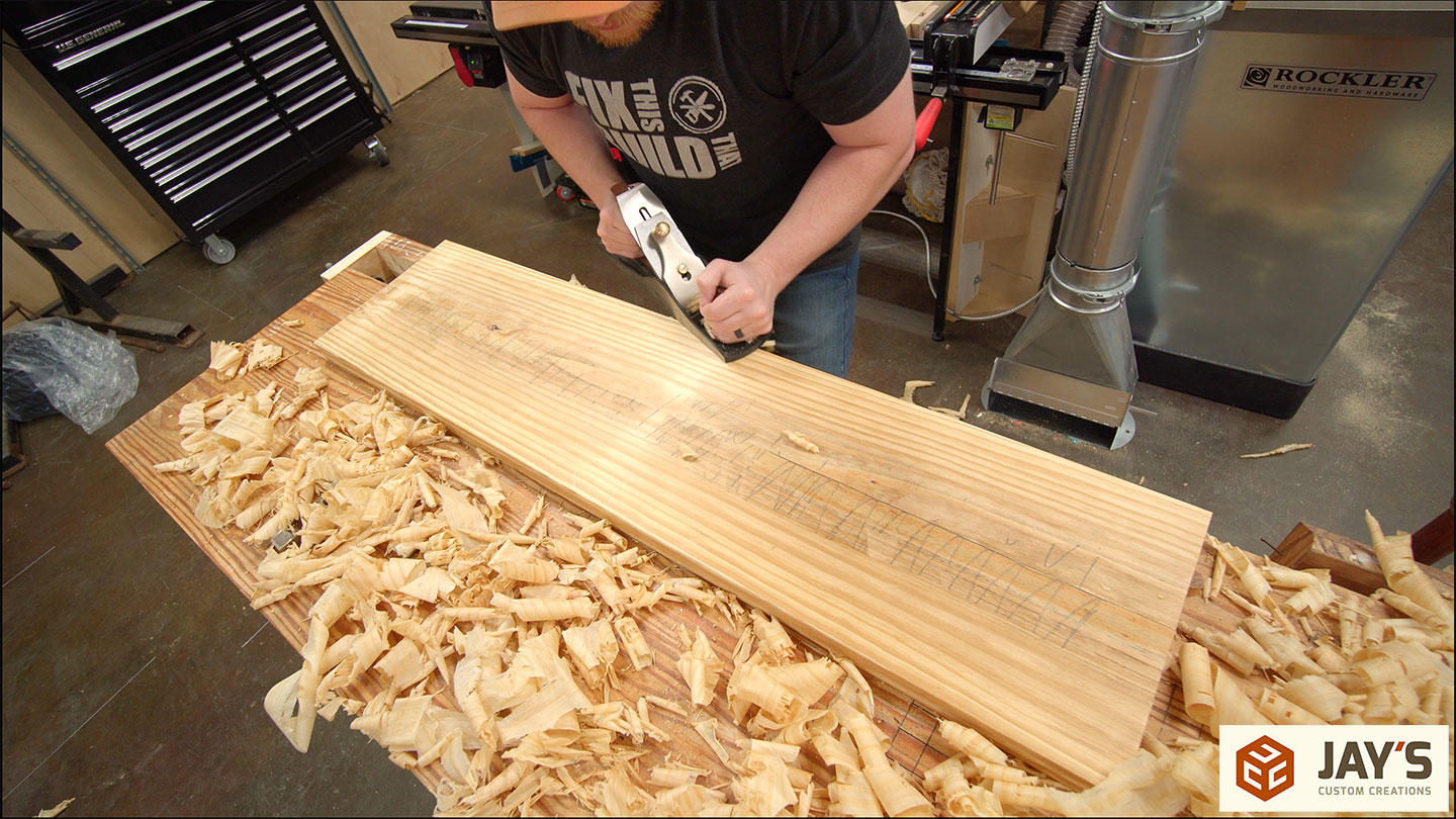
While probably completely unnecessary, just like me, I followed up with a 4-1/2 smoothing plane to make the surface that nobody will ever be able to touch perfectly smooth.
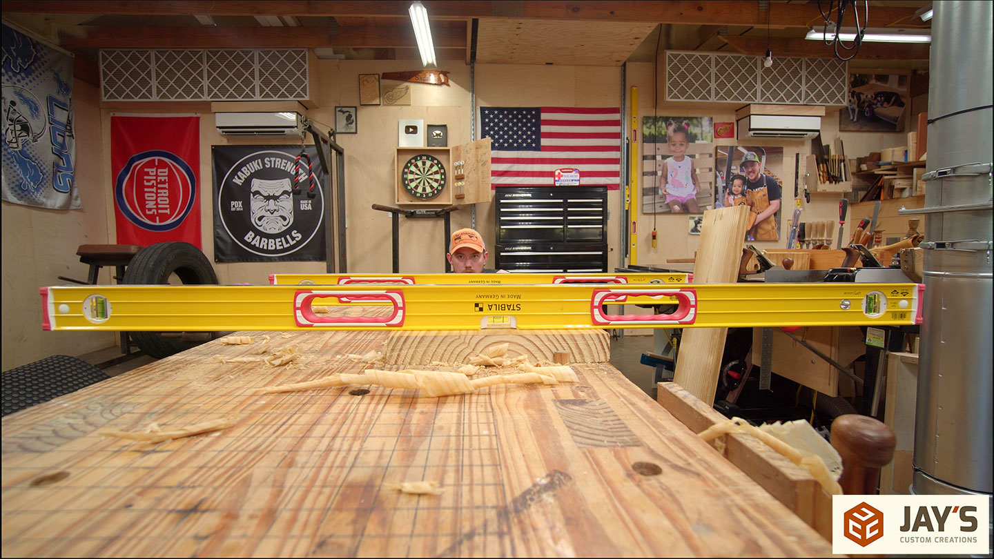
From here it’s a rinse and repeat process for the other three wide faces of the top assembly. Except we’re not rinsing anything. We’re just repeating. Oh, and it’s a good idea to use winding sticks to make sure the boards aren’t twisted.
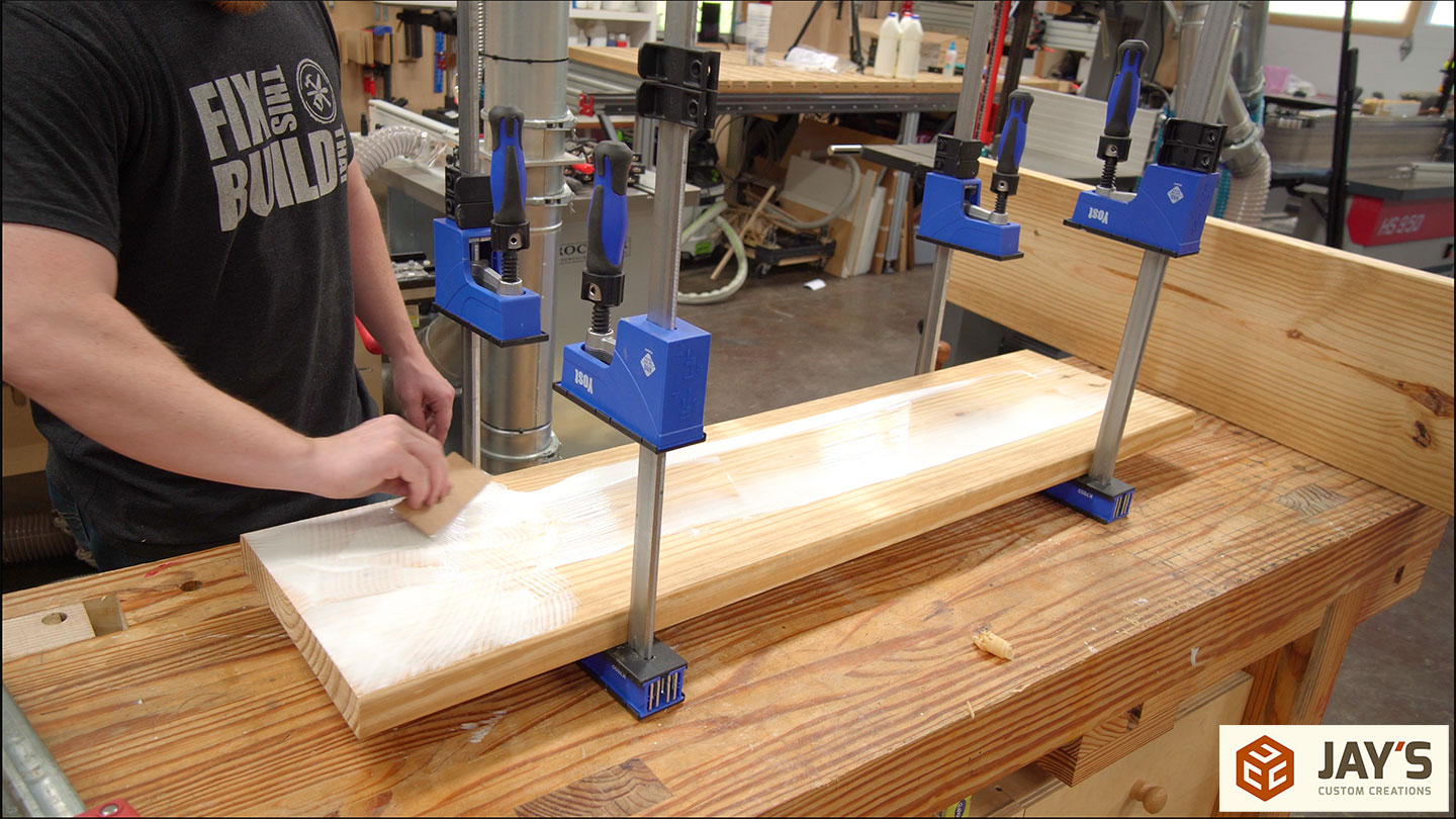
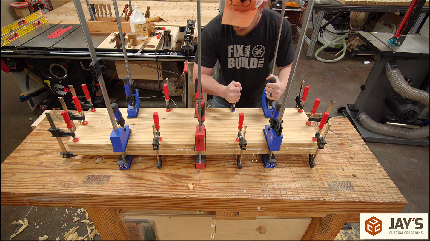
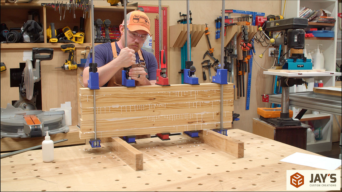
To glue the boards together I used glue. And of course clamps. But that part is always obvious.
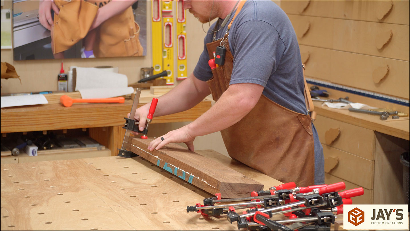
After a cold plunge and night of rehab on my shoulders from the hand planing work, I got to work on the edge of the glued-up panel.
It was somewhere around here I realized two things. First, I was watching way too many Drew Fisher videos, and second, I spent way too much time the past two days trying to use nothing but hand tools.
At this point, I walked away from the project for a week or so while I had contractors working in my backyard starting in on an outdoor kitchen project. When I got back to the build I had no interest in finishing it with just hand tools. Power tools to the rescue! I started, once again, by milling some material for the legs. And gluing together the four leg blanks.

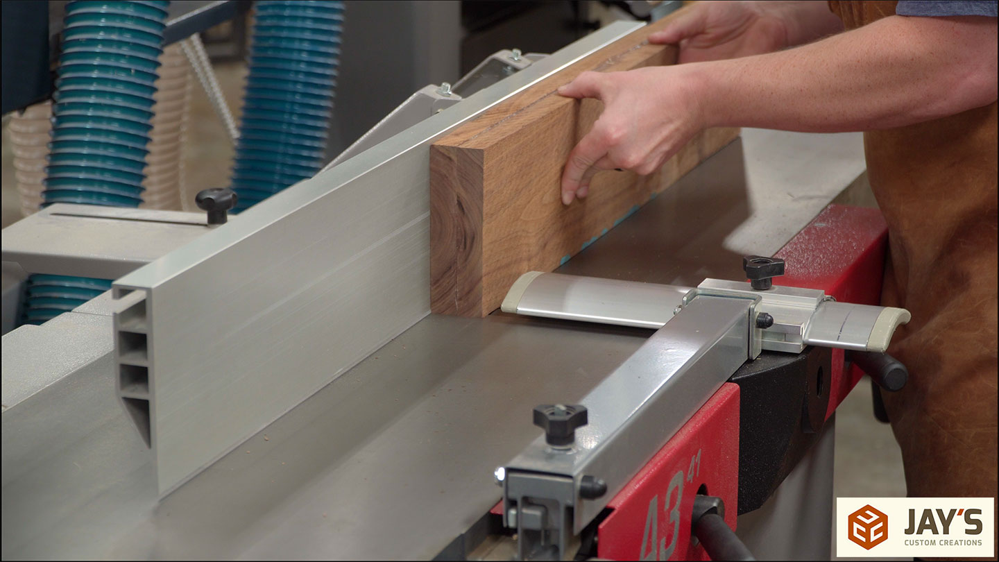
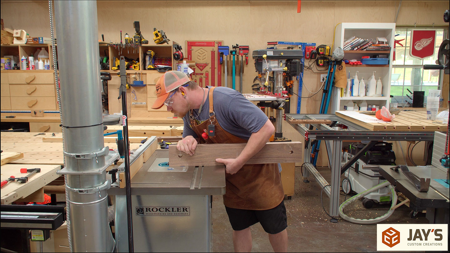
With three of the faces already taken care of I continued cutting down the top panel to its final size.
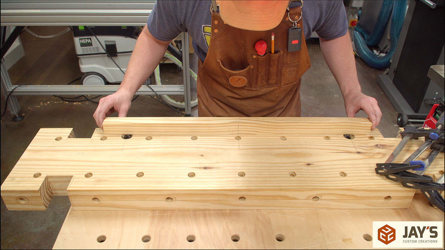
While previously building the Matchfit version, I screwed up the leg dados in the top piece and had to remake the top. In an effort to not start a trend I took the time to mark out the locations of all the finished geometry on the top panel.

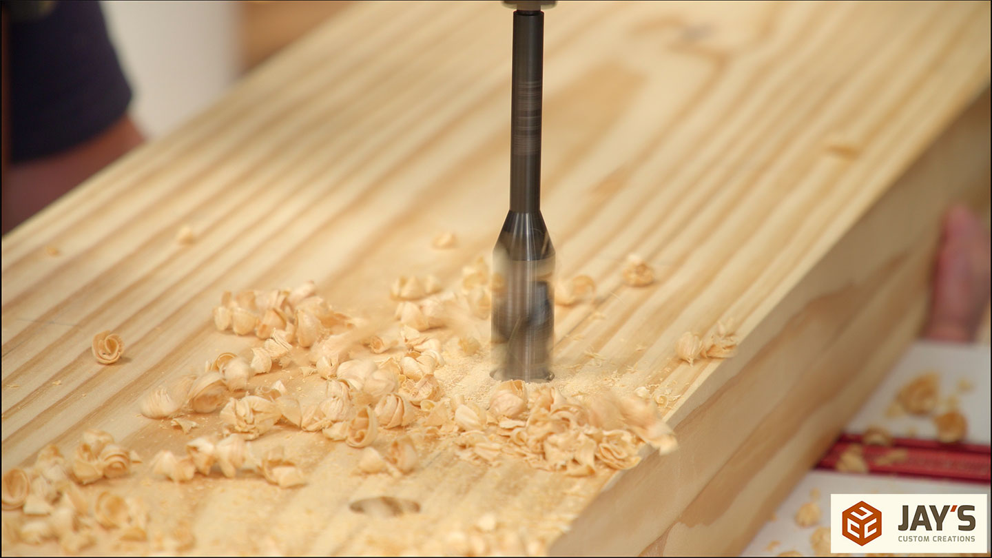
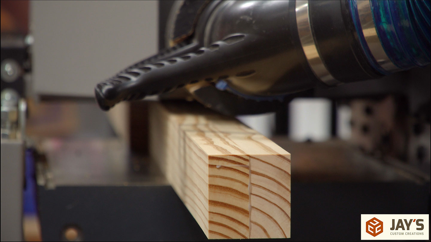
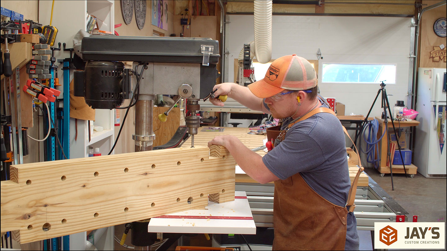
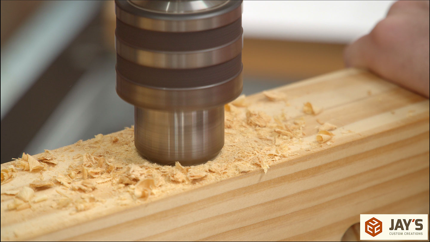
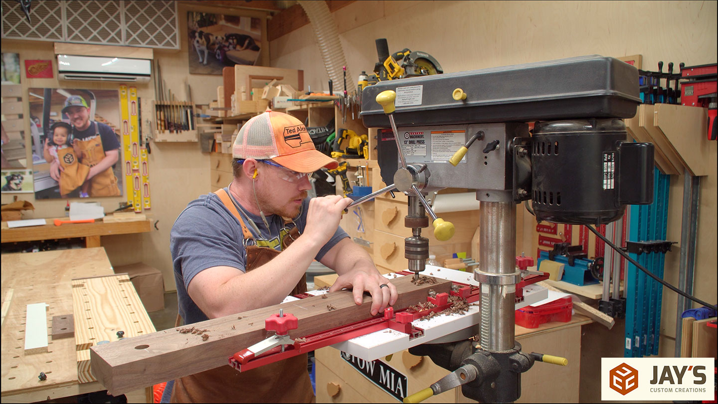
I needed the completed legs to size the dado’s for the leg-to-top connection and because they were still in clamps I started drilling the dog holes instead. This is an overdrive bit in the drill press. It has the speed of an auger bit but the cut quality of a Forstner bit. These bits also produce a clean exit hole.
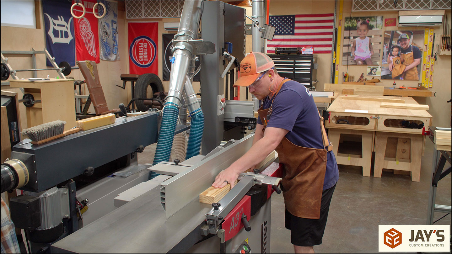
I gave the leg blanks a couple of hours in clamps and then milled them to their final size.


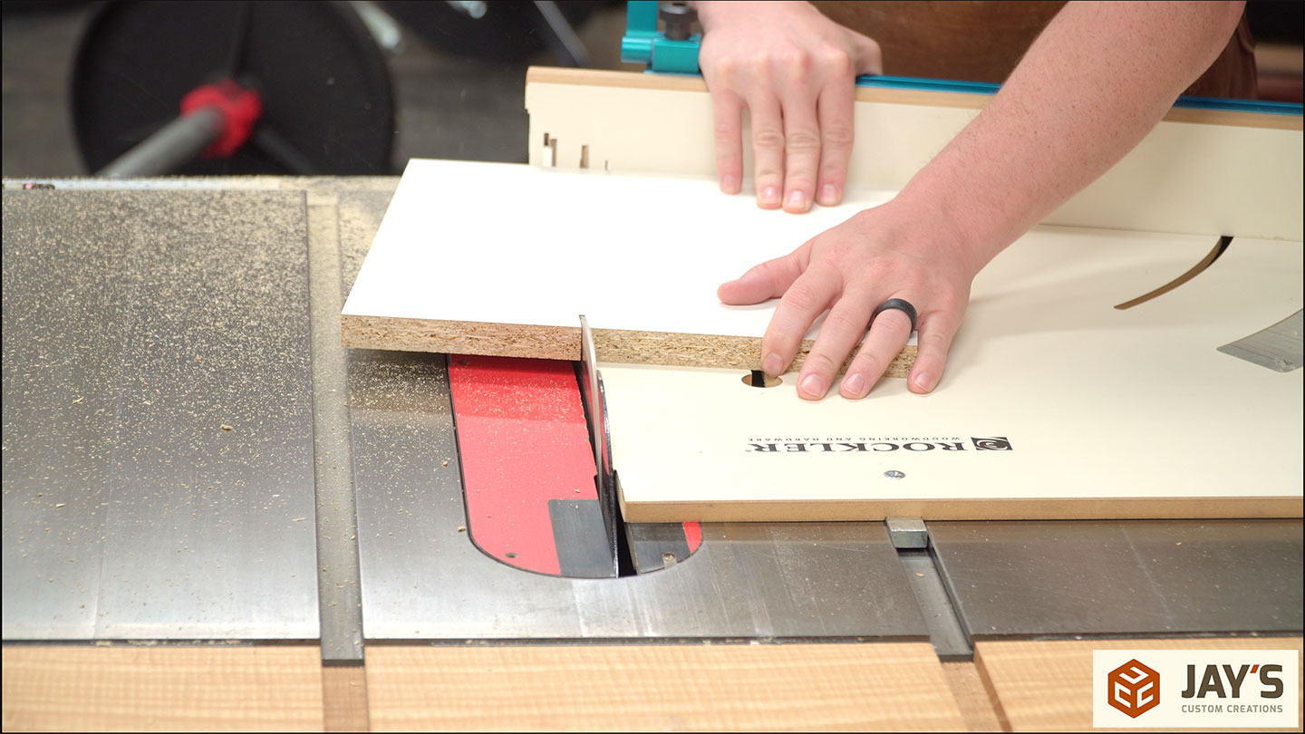
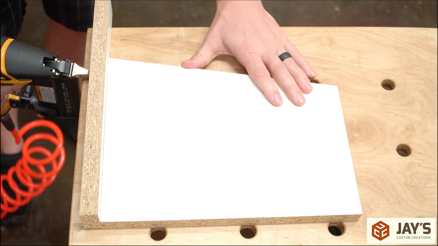
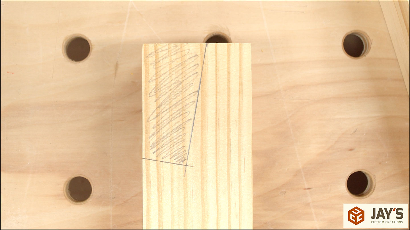
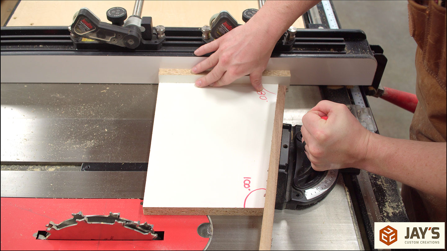
Just like with the Matchfit version, I made a quick jig to cut the angled notch on the top of the legs. It’s just an angled piece of scrap sheet material with a stop on one end.
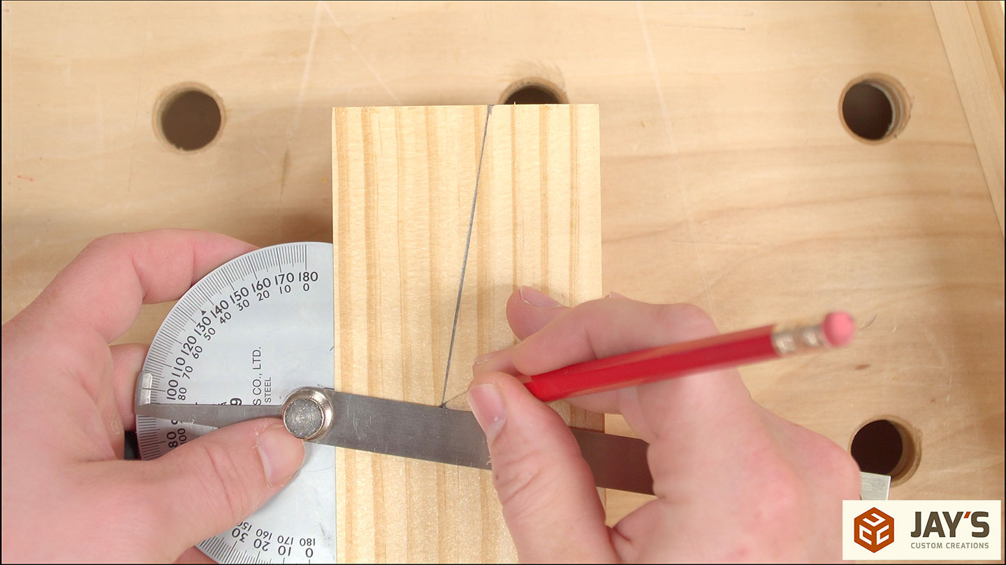
The notch cuts are then drawn onto the legs to make sure I don’t cut on the wrong faces.
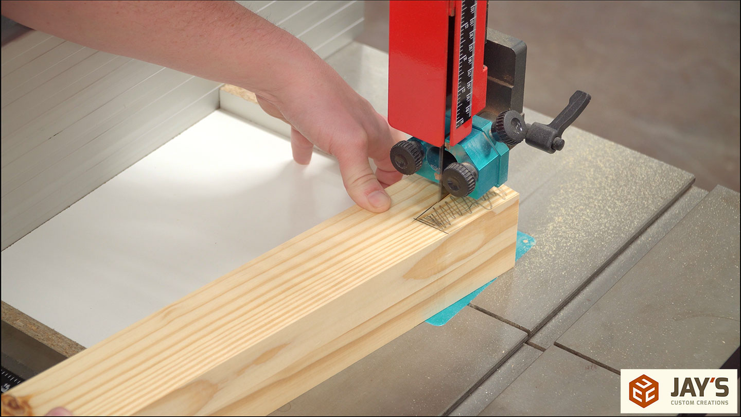
Here you can see how the jig works. No toggle clamps or hold-downs. It’s just an angled reference face that rides against the fence.

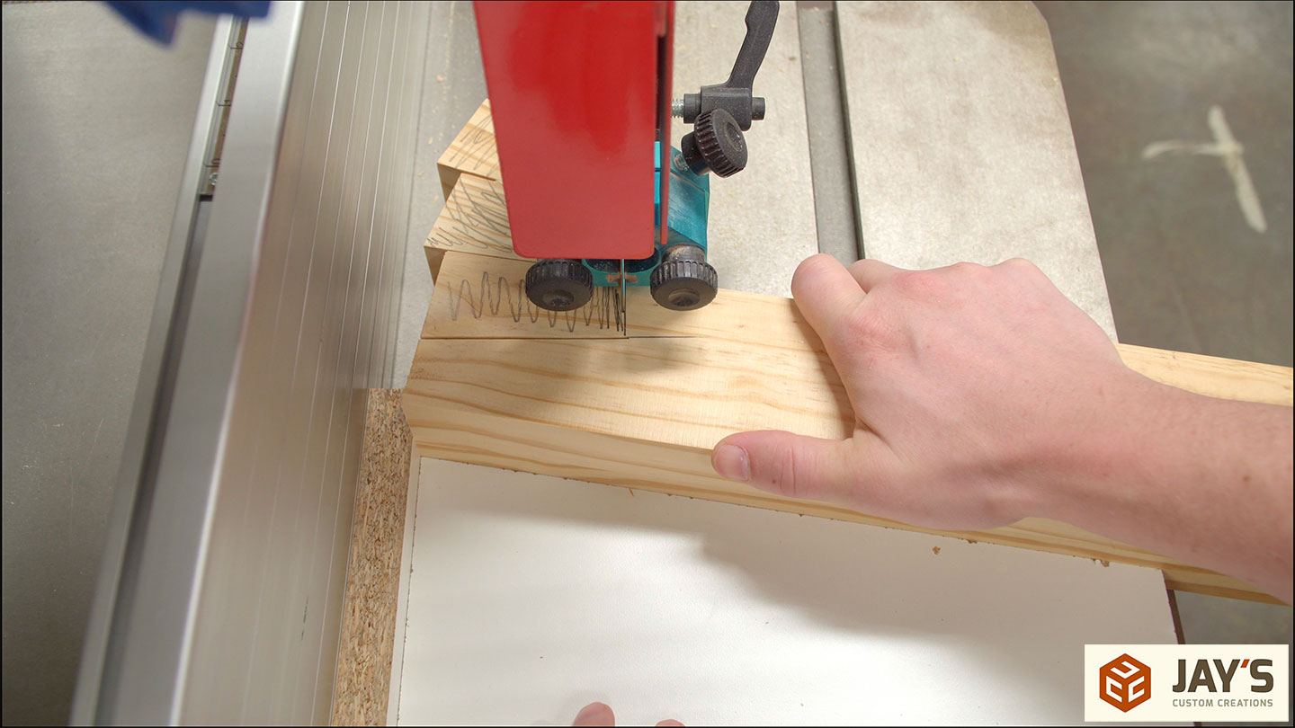
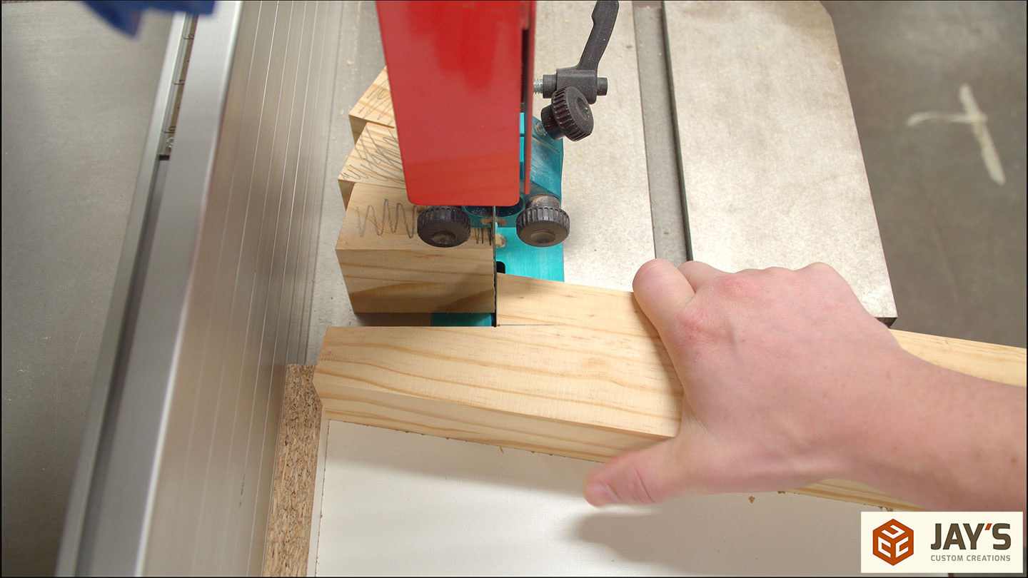
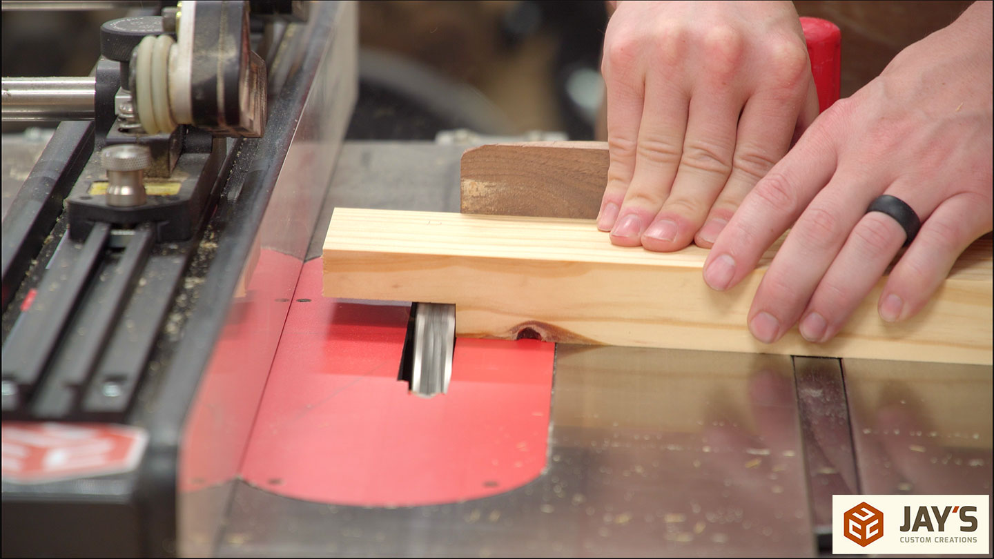
After all the cuts are made in one direction the jig is rotated 90 degrees and the second cut is made. This is essentially creating a 90-degree corner that is on a specific angle from the length of the board.

With the legs done I now knew the exact width needed for the top dados. In the Matchfit version, I used a single table saw blade to nibble the material away. That was way more work than I initially thought due to the size of the panel I was moving across the saw. So I took the time to set up my dado stack for a 3/4” bite per pass.
The fit I achieved was borderline too tight. But I know that these legs will shrink over time. I’d much rather deal with a frustratingly tight fit at first than a super sloppy joint down the road.
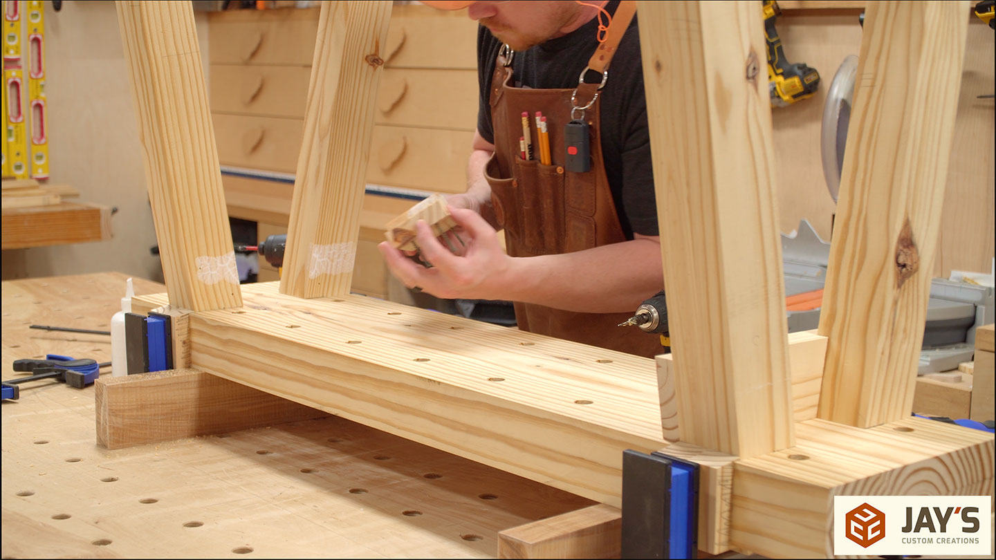
The offcuts from the bandsaw are perfect to use as clamping cauls to make sure the legs are positioned tightly where they need to be. Then the stretchers can be set in place and traced.
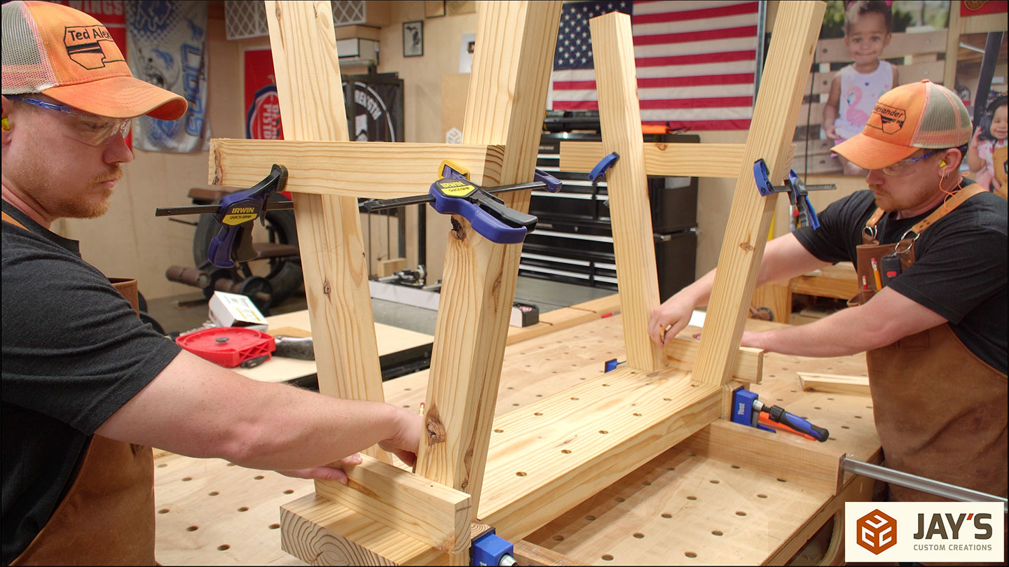
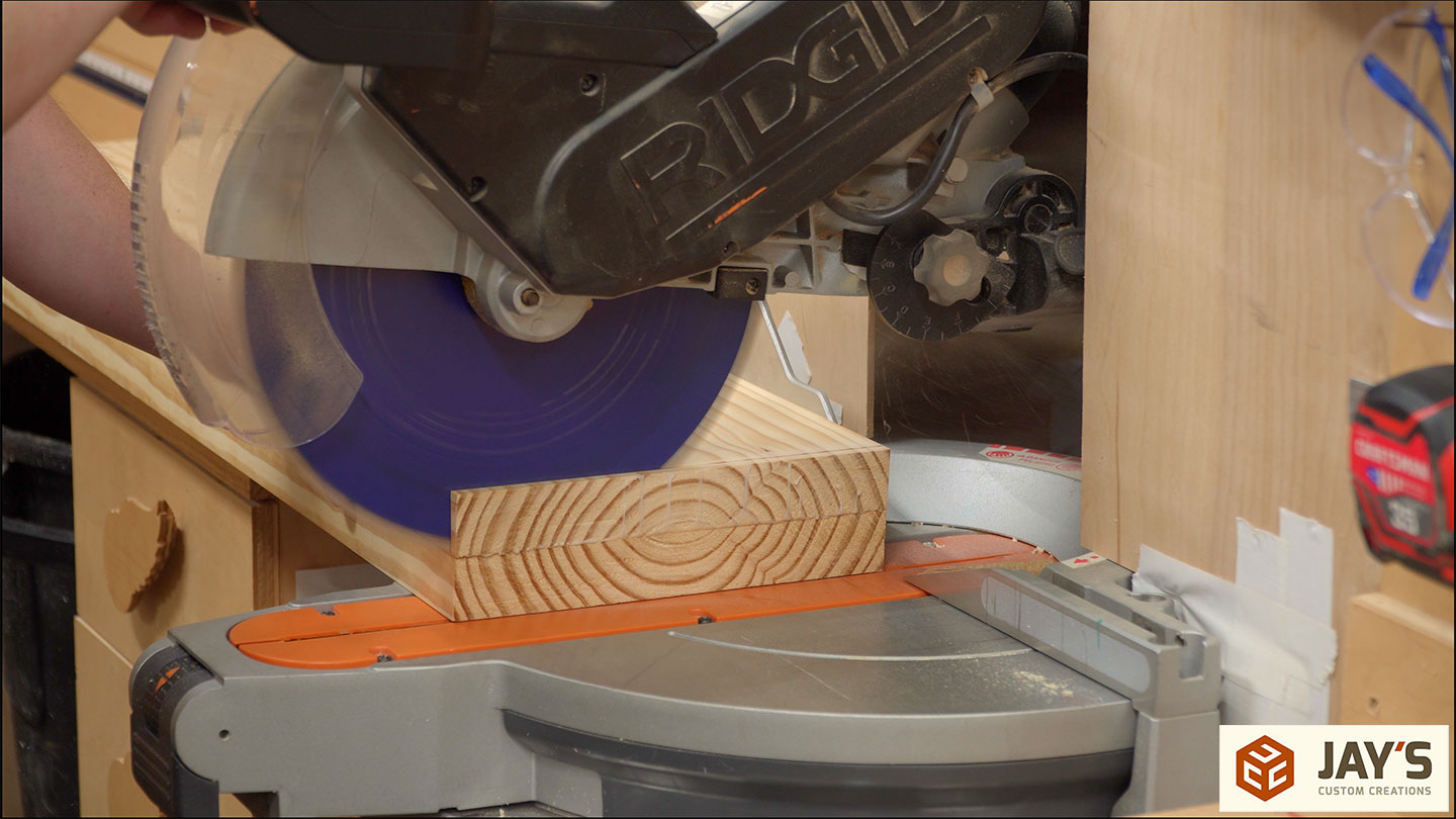
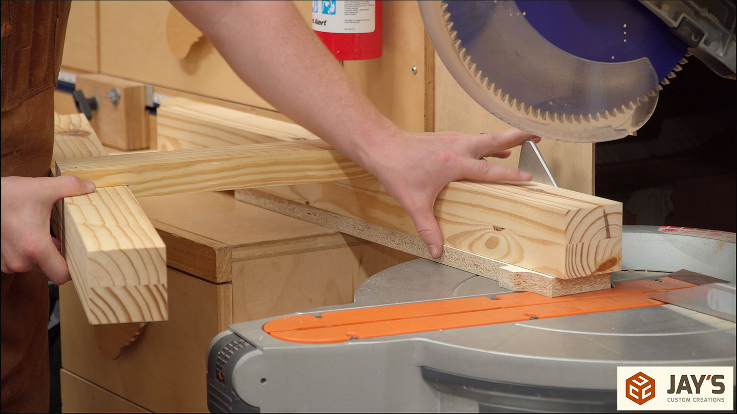
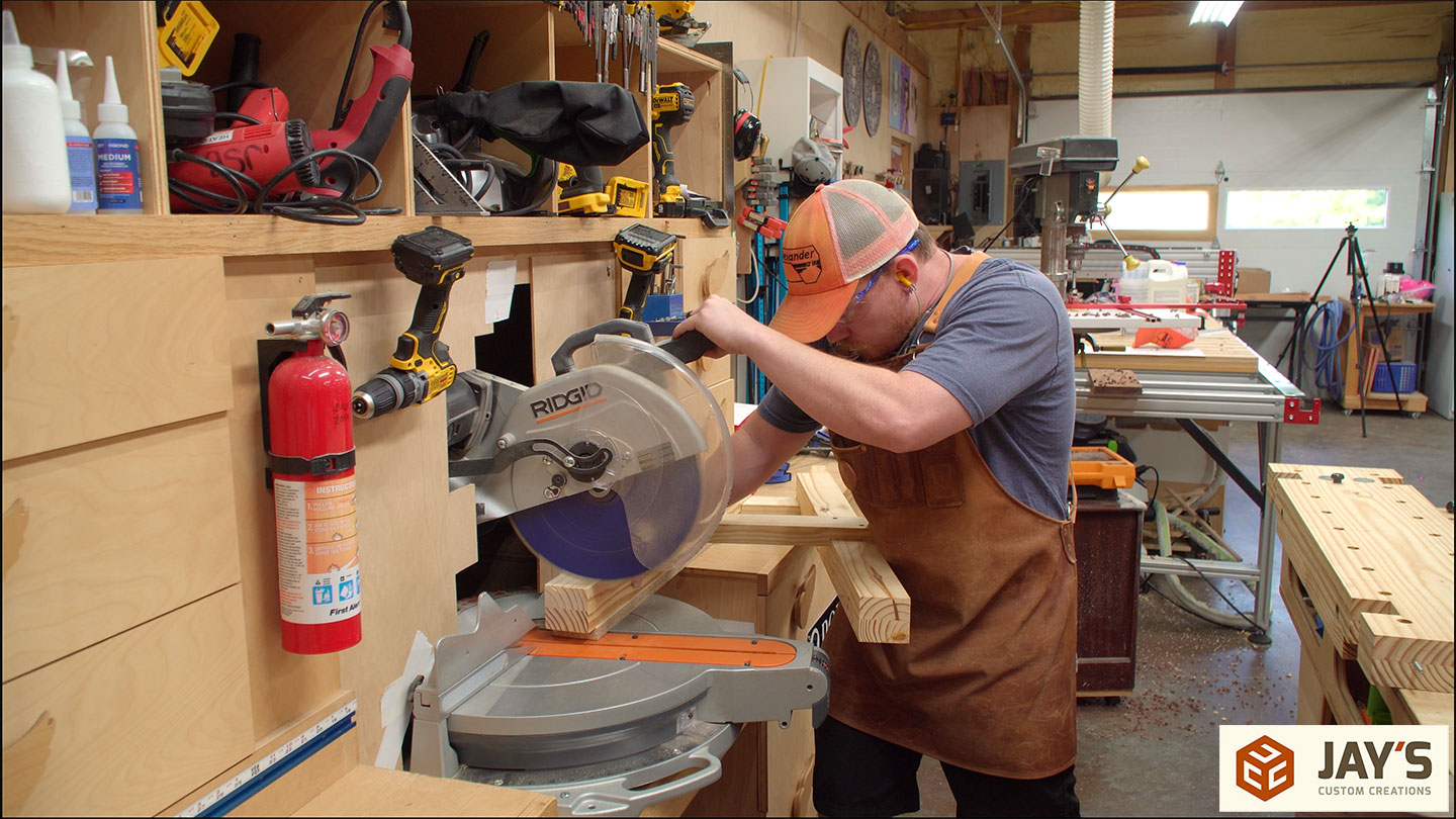
All of the stretchers are first cut to length at the miter saw and then a matching angled rabbit cut is made on each end. The depth of cut isn’t too critical here. Removing anything less than half the thickness will work.

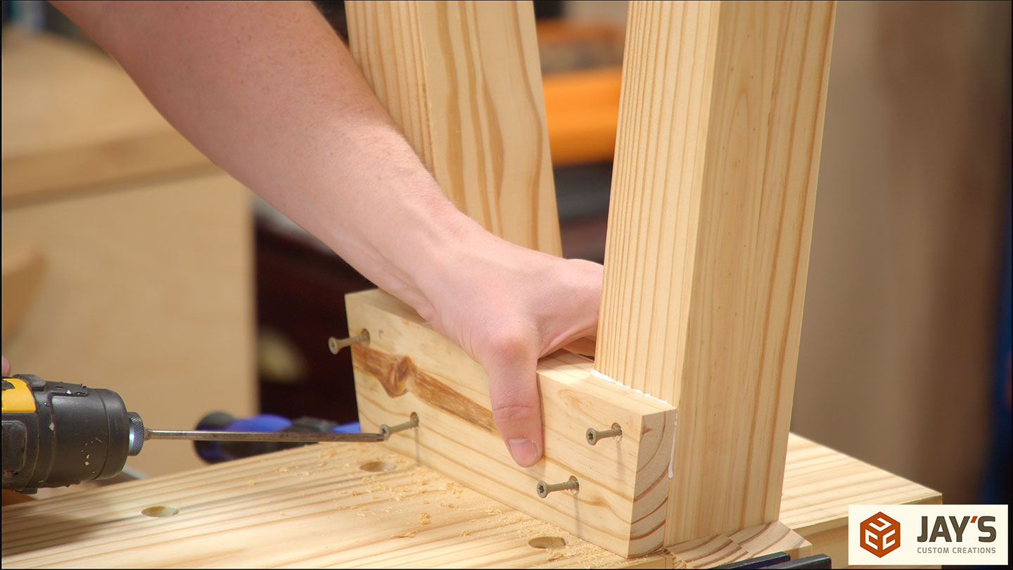
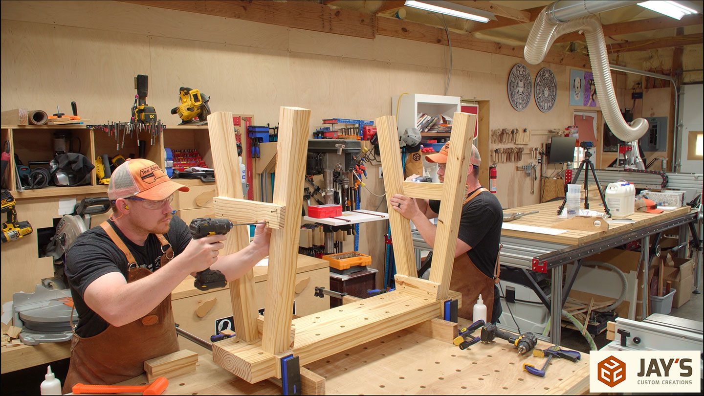
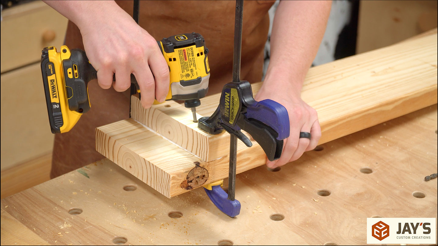
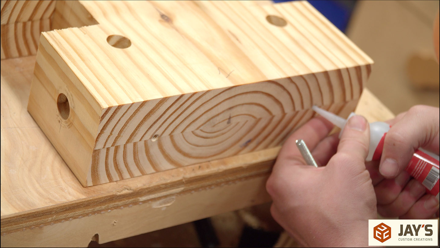
To install them, a little bit of glue and two screws per joint is used. For the short stretchers that will be touching the bottom of the top panel, I made sure to keep the glue away from the top panel. Just to make sure I don’t accidentally glue the legs to the top.

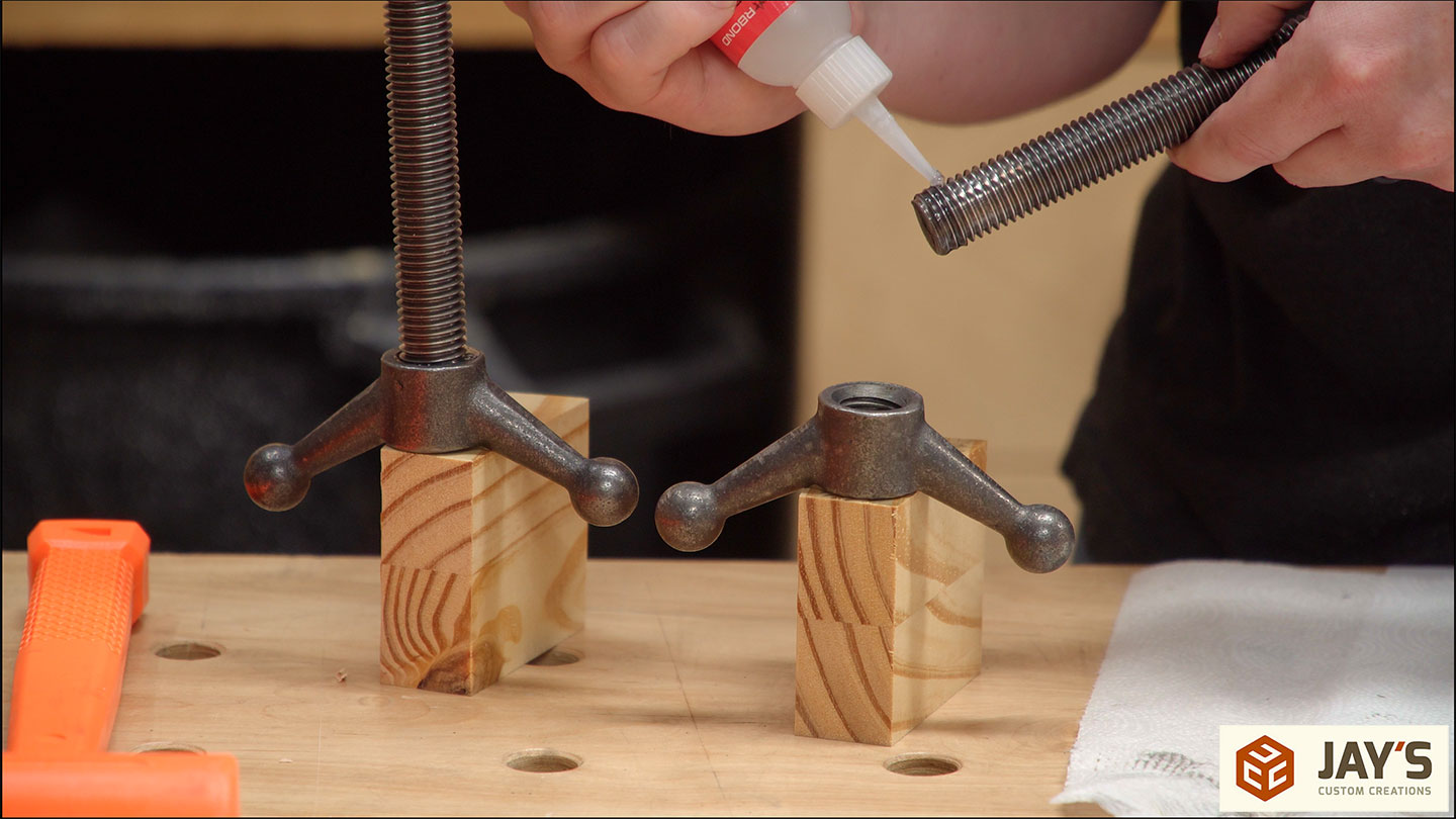
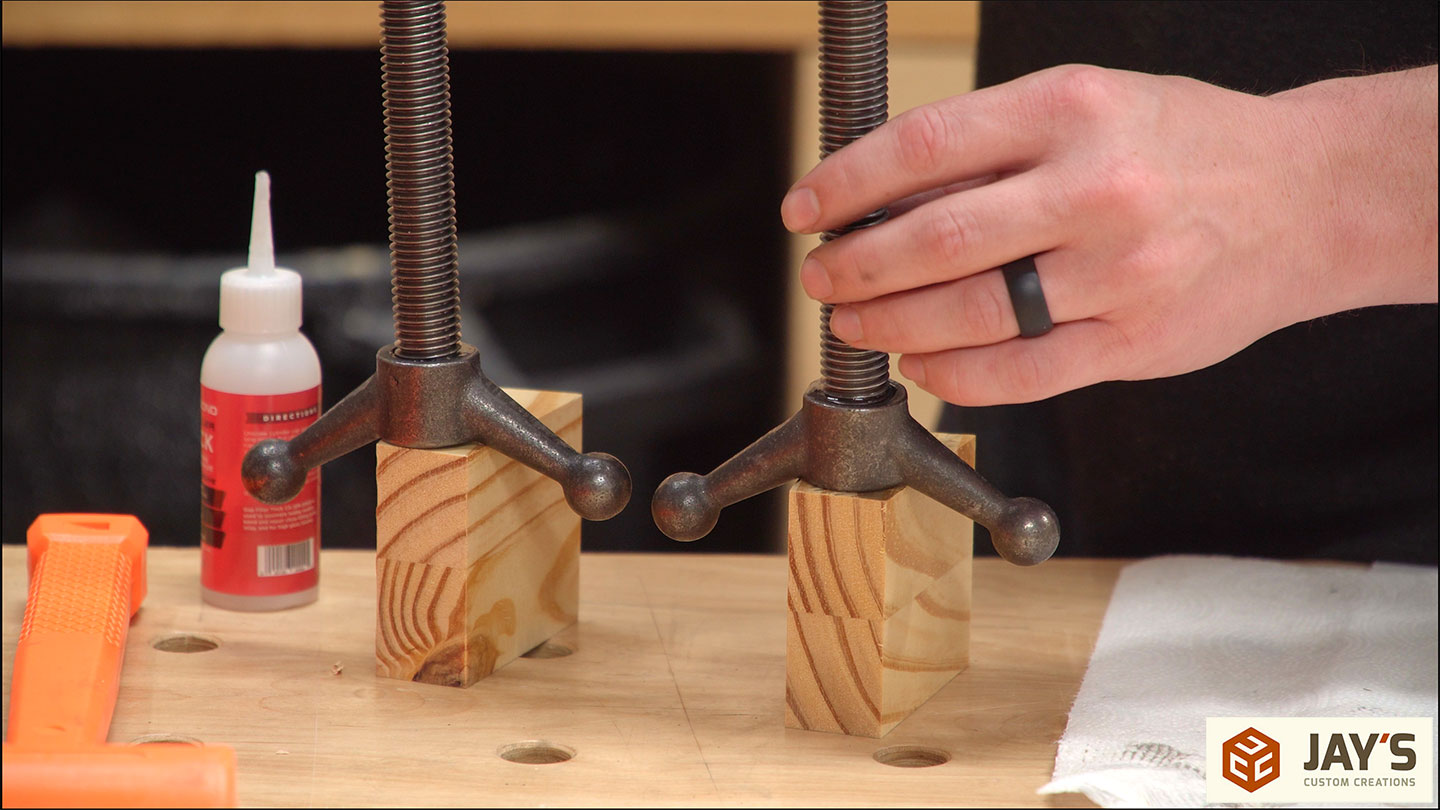
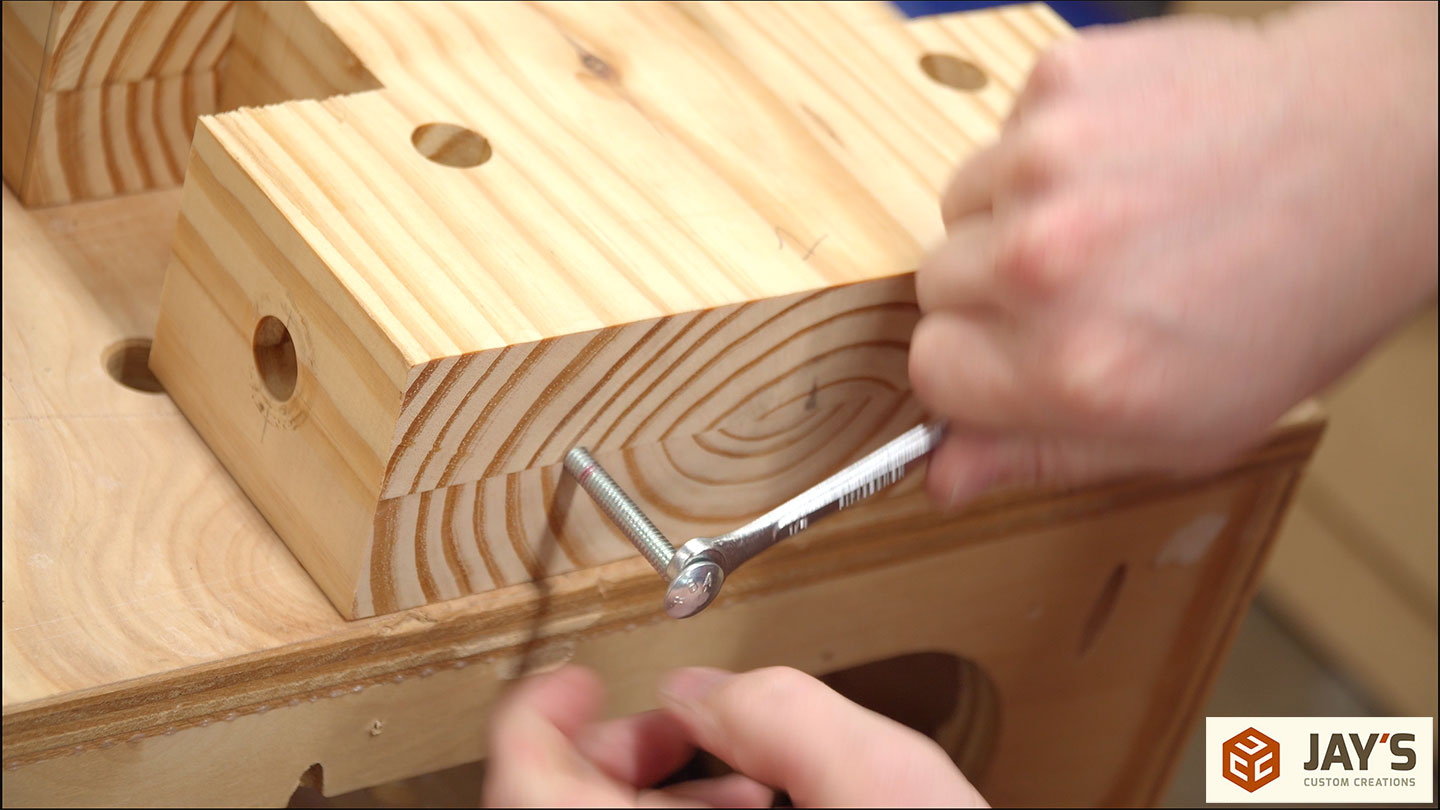
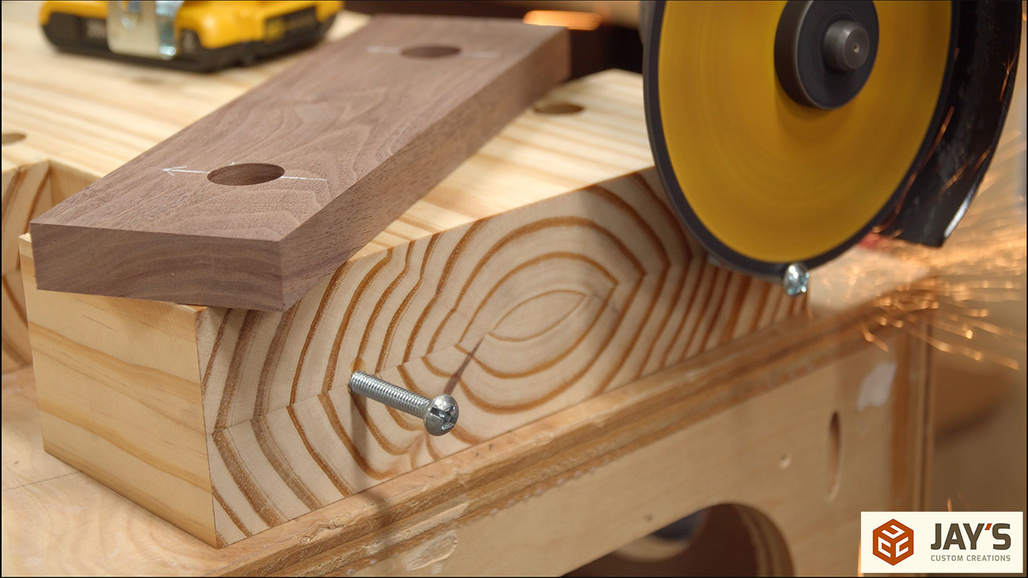
Here’s something I should have done earlier. The threaded rod needs to be secured to the handles. For that, I used thick CA glue. A better option would have been to use a medium-thread locker. But this got the job done.
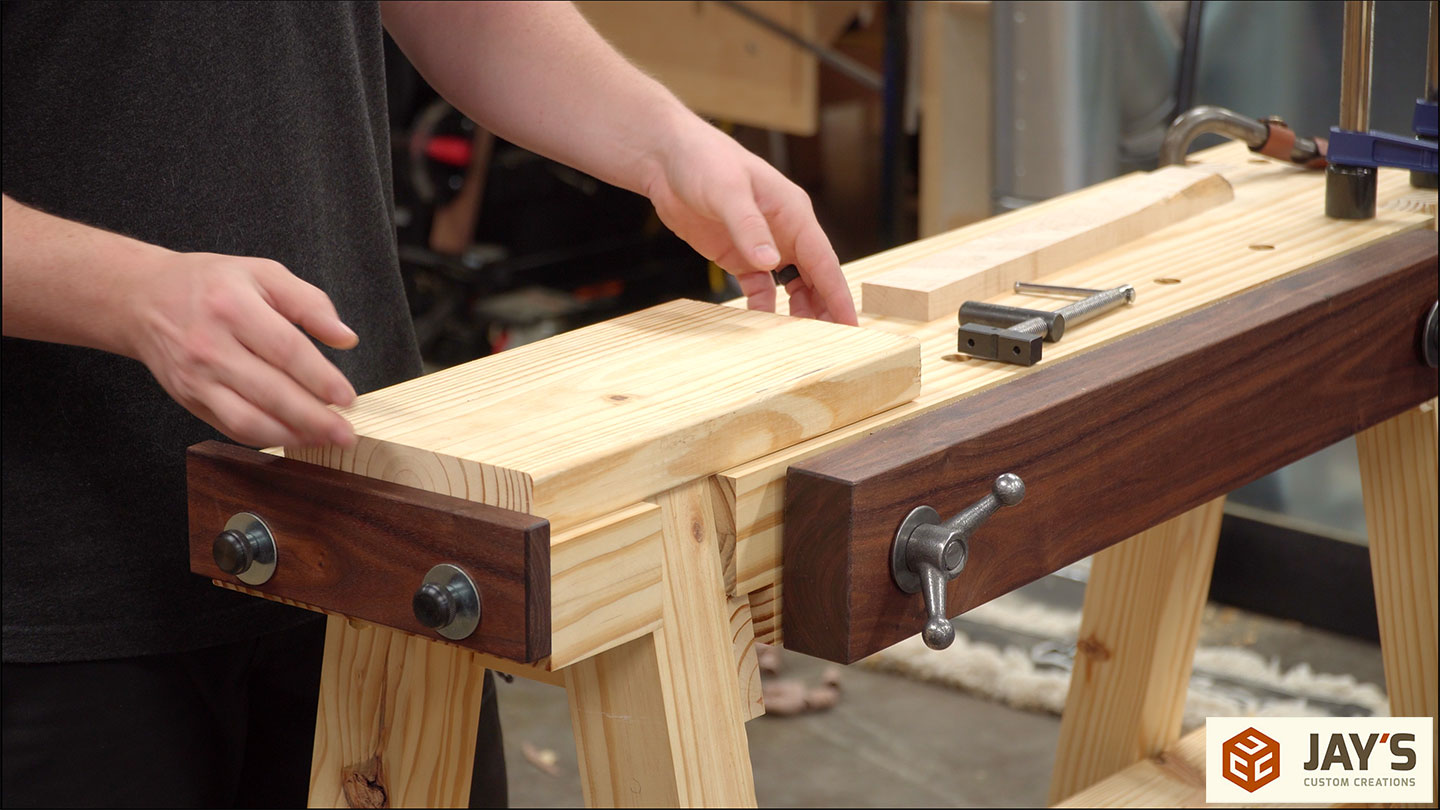
While the glue dried on the leg assemblies I started on the lower shelf. This shelf is incredibly simple. It’s just a piece of 2×8 or 2×6 cut to overhang the lower stretchers by a couple of inches. One small offcut of the same board is needed to act as a stop.

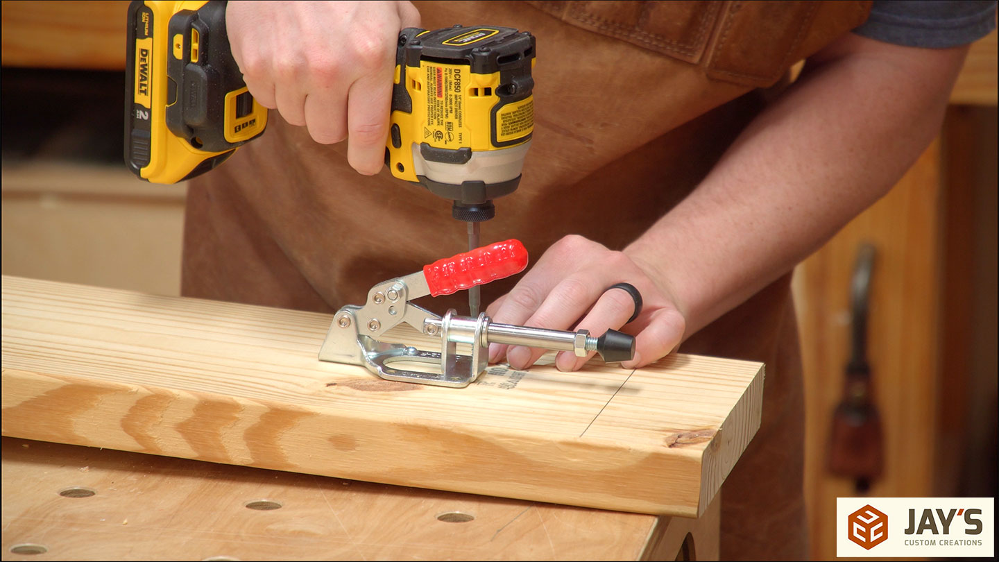
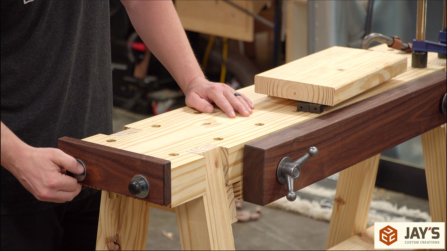
The stop is glued in place on one end and a linear clamp is screwed in place on the other end.
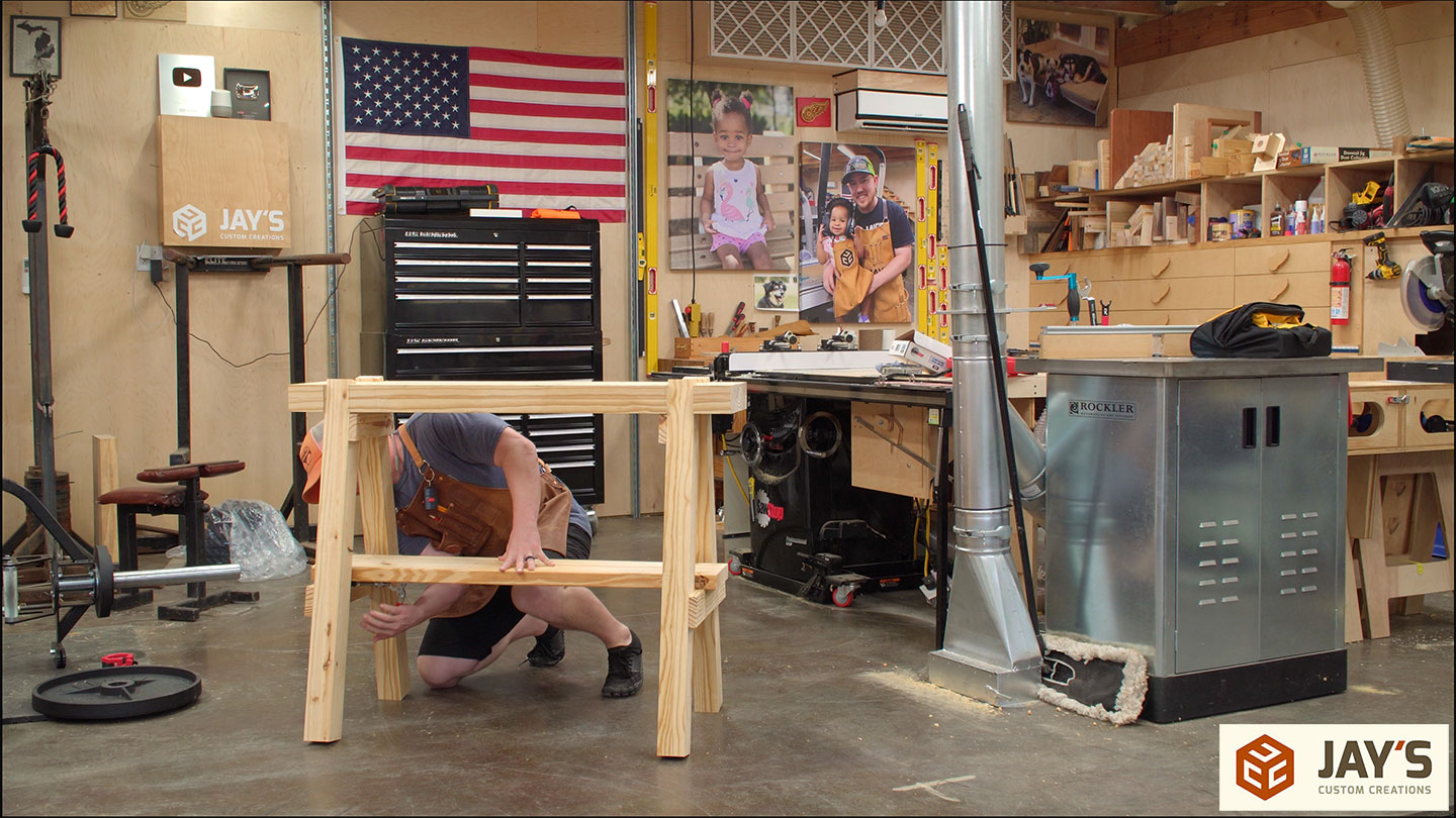
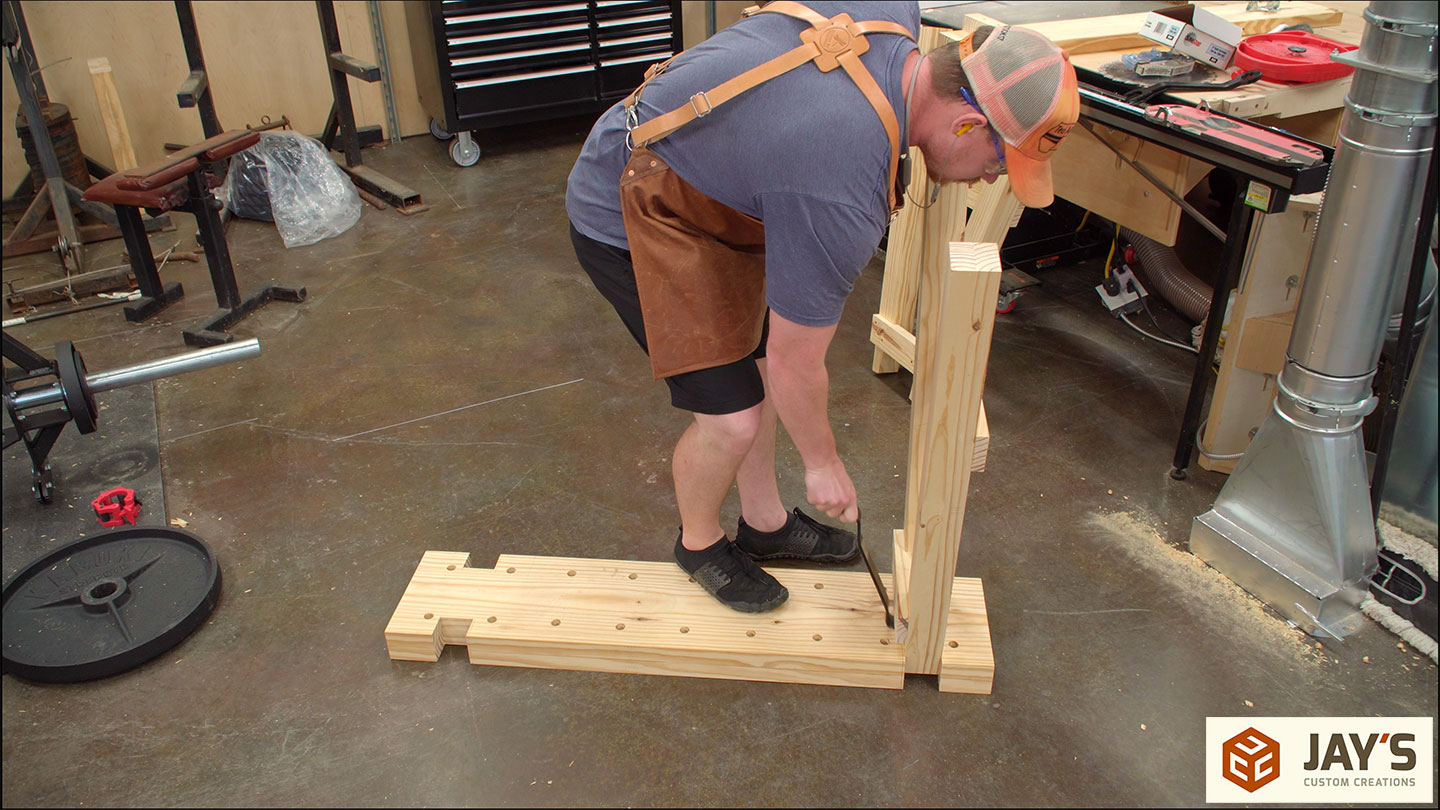
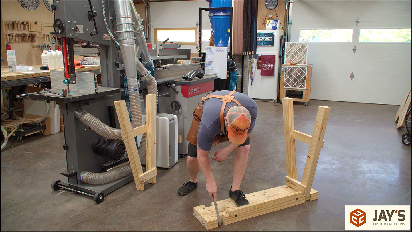
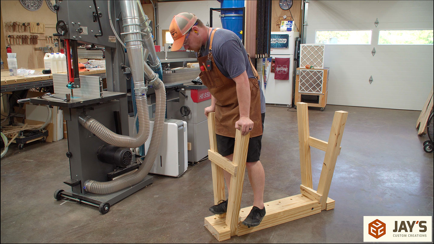
Now that the structure is done I can take it apart and work on some more details. It turns out the leg-to-top joints were a bit too tight. I had to use a pry bar to remove one of them.

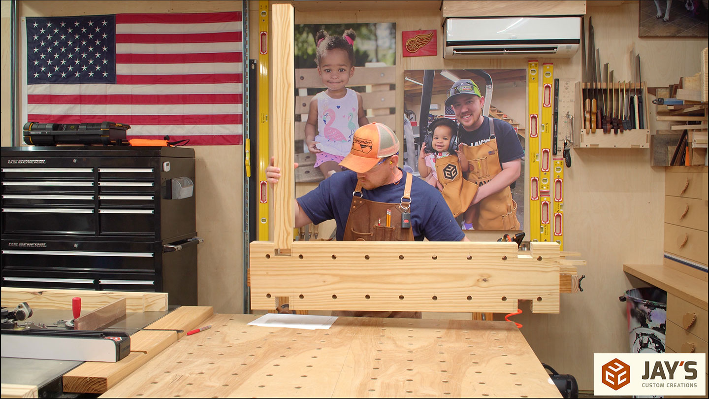
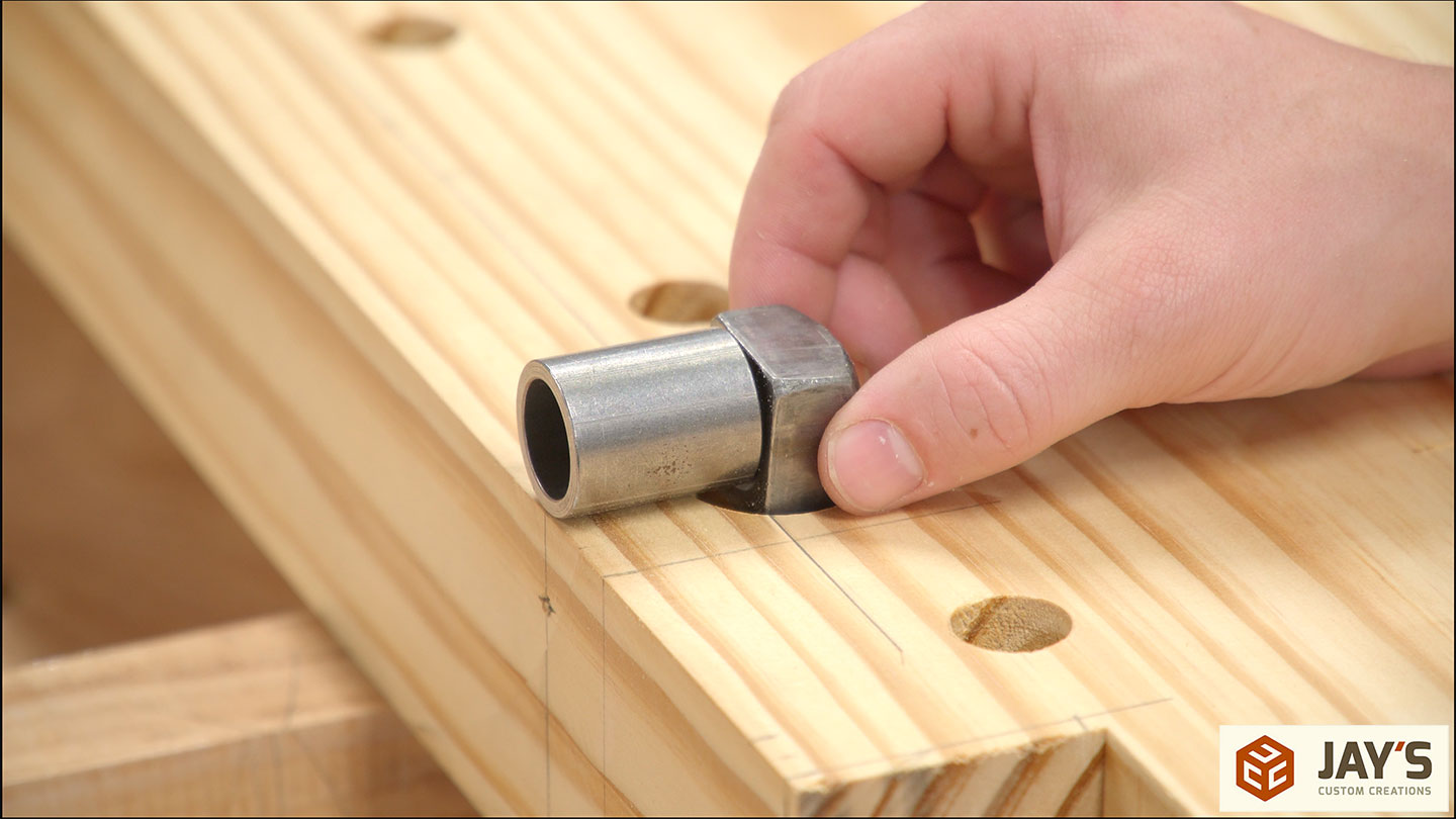
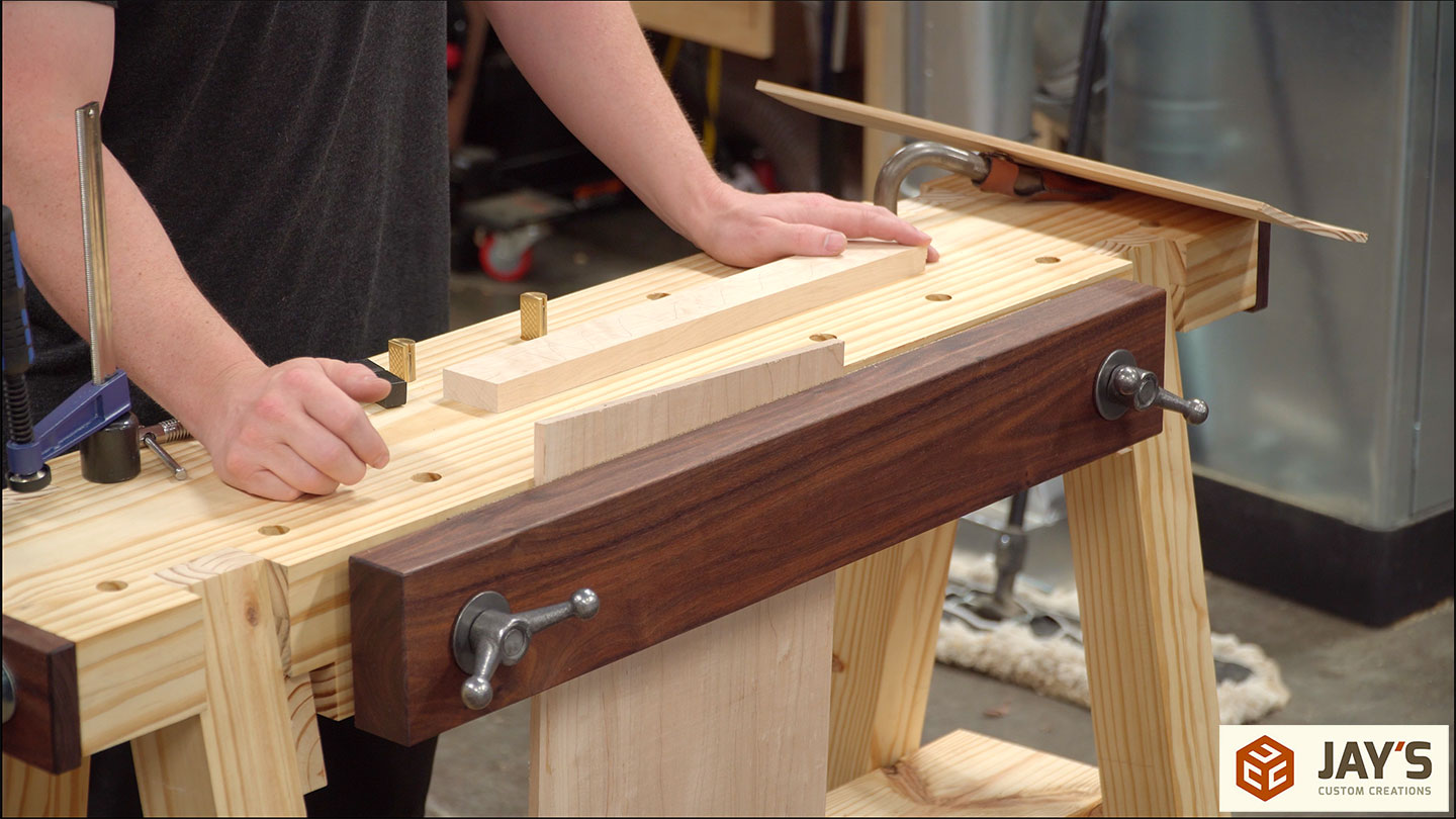
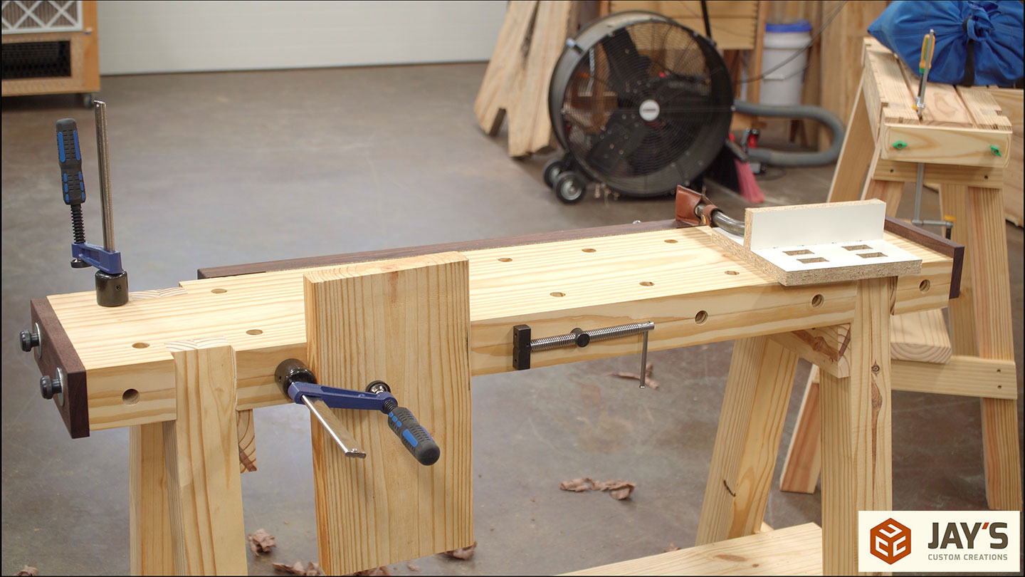
To be a little more consistent in the front vise hardware locations I made a simple story board. The board has a marked centerline that is lined up with a marked centerline on the top. It’s cut to the exact length between the centers of the vise screws
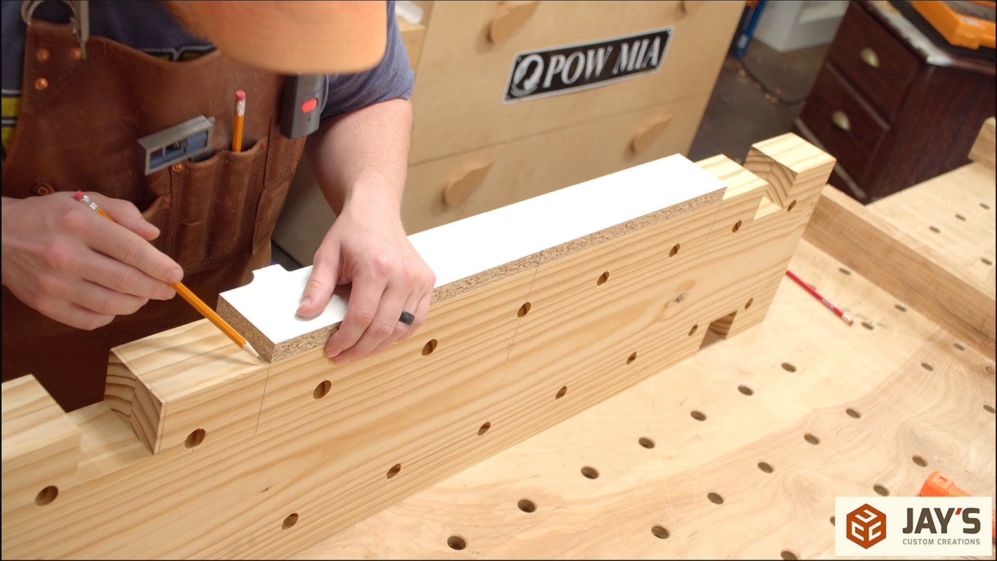
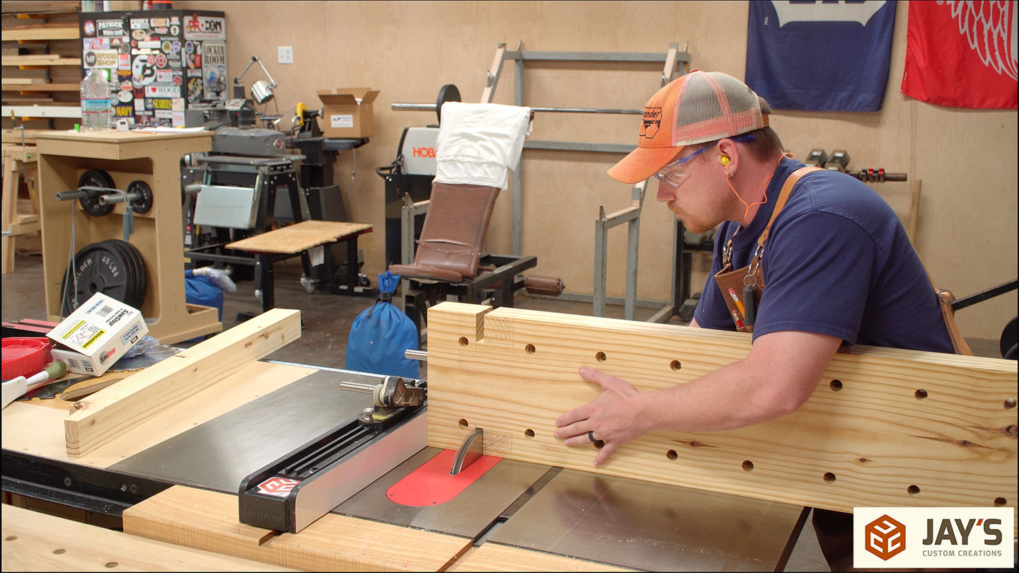
A board will be glued to the bottom to build up the bench side of the vise but first, the nut mortise needs to be cut. The board is set in place and the nut location is traced out.
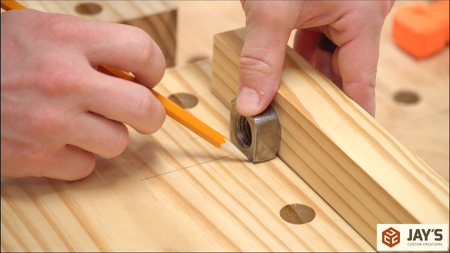
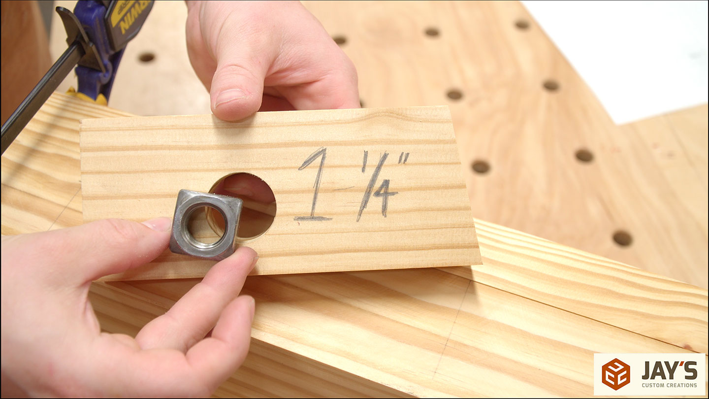
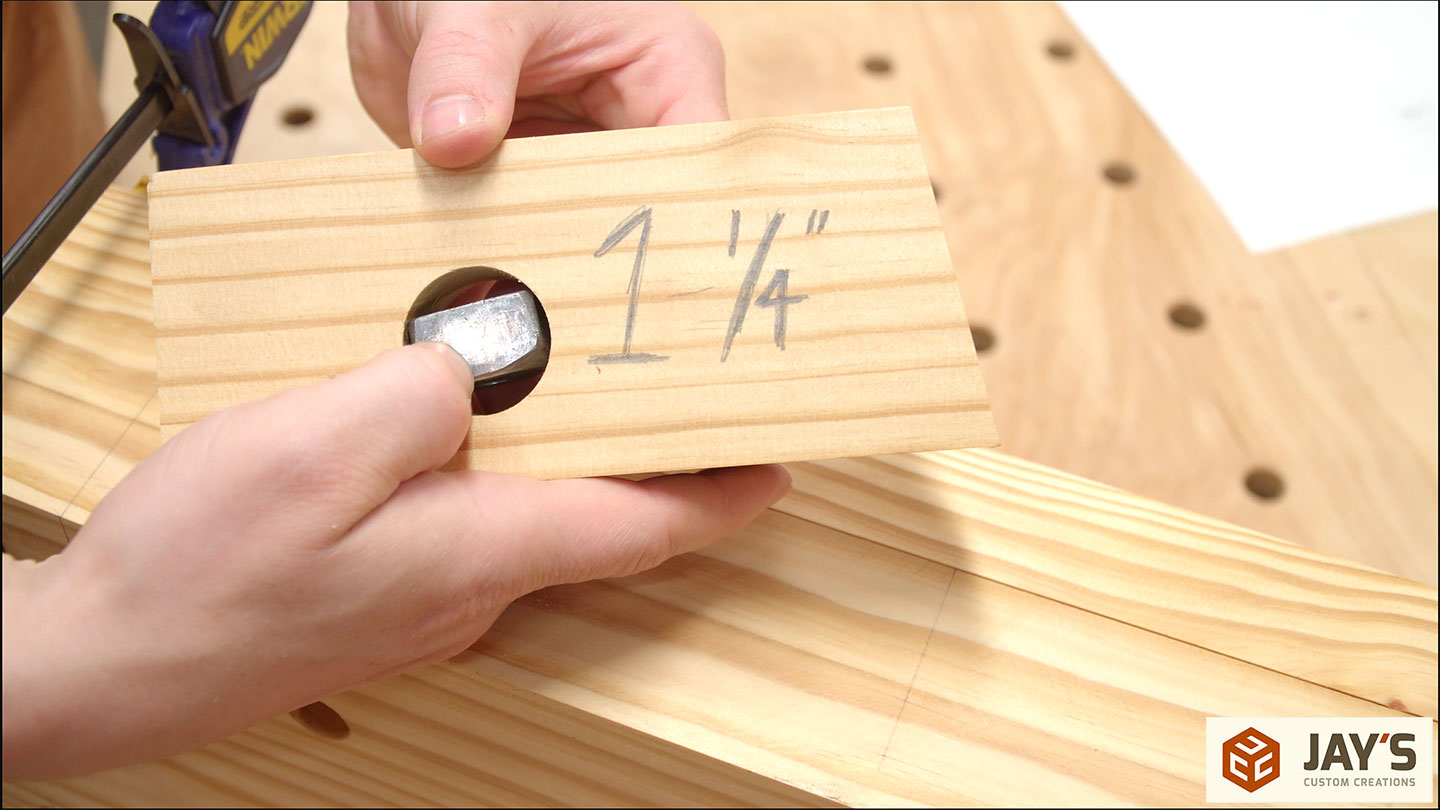
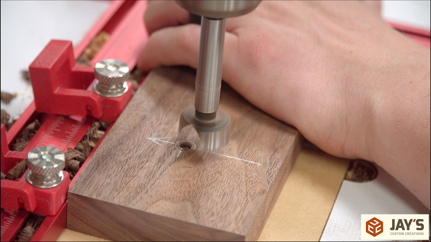
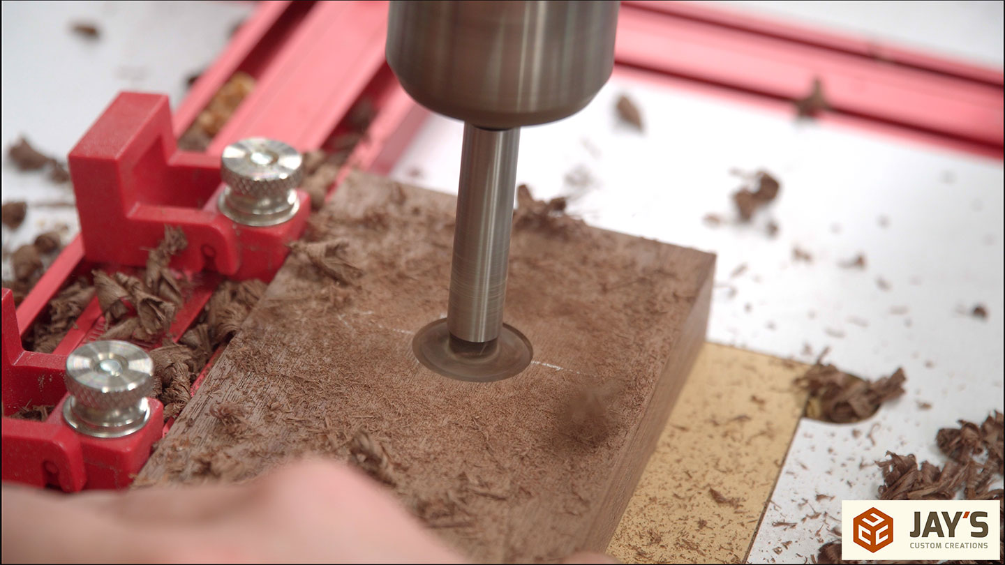
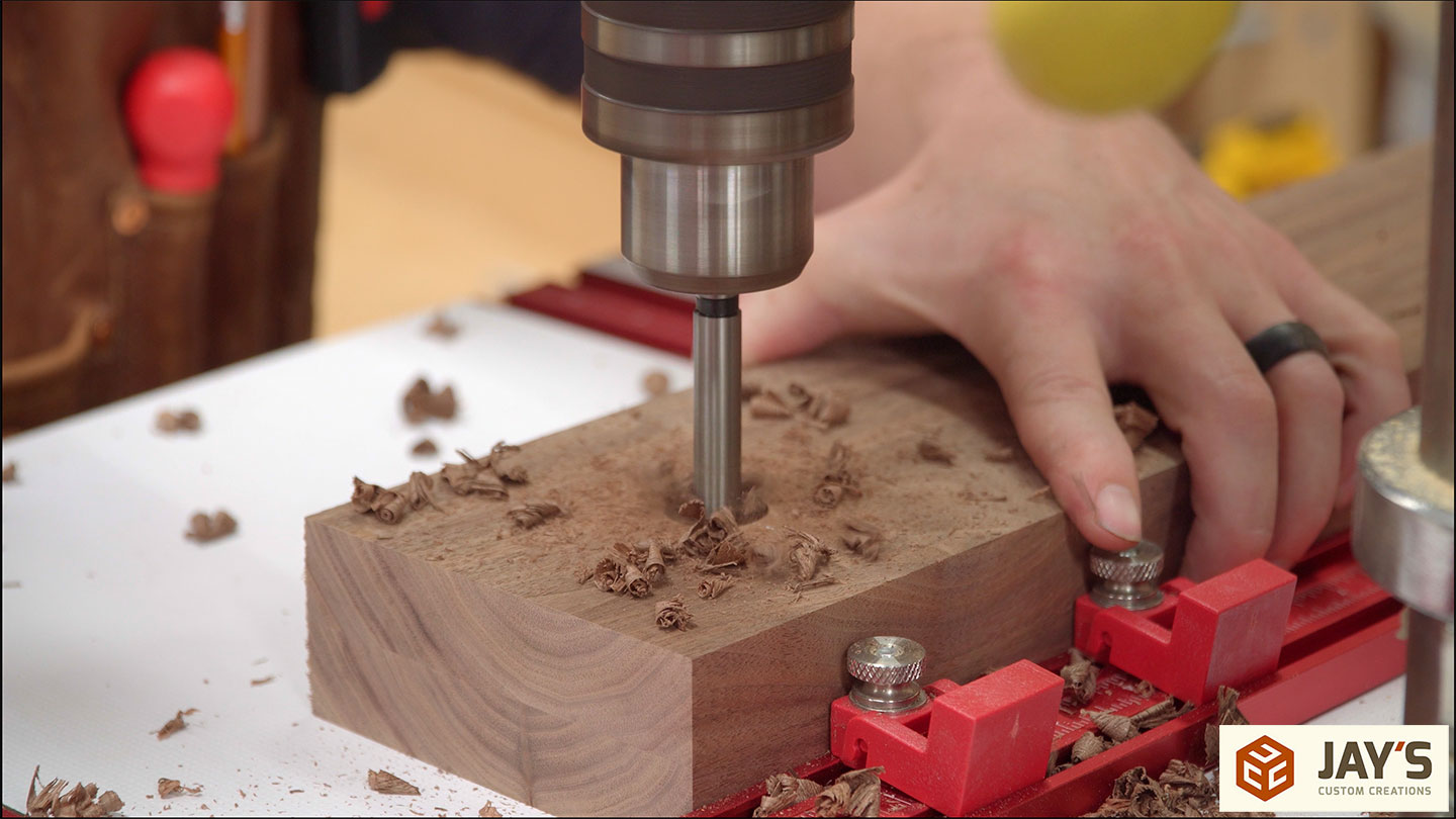
One really nice thing about a square nut is that it will not rotate in a round hole as much as a hex nut. In this case, a 1-1/4” hole captures the nut quite well. This means the drill press can be used to drill a mortise rather than a router and edge guide or chisels.
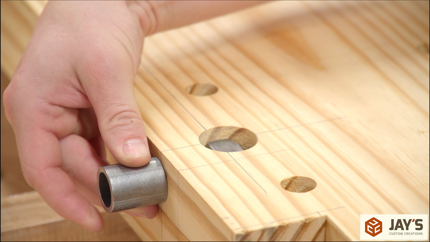
With the locations marked the holes are drilled.

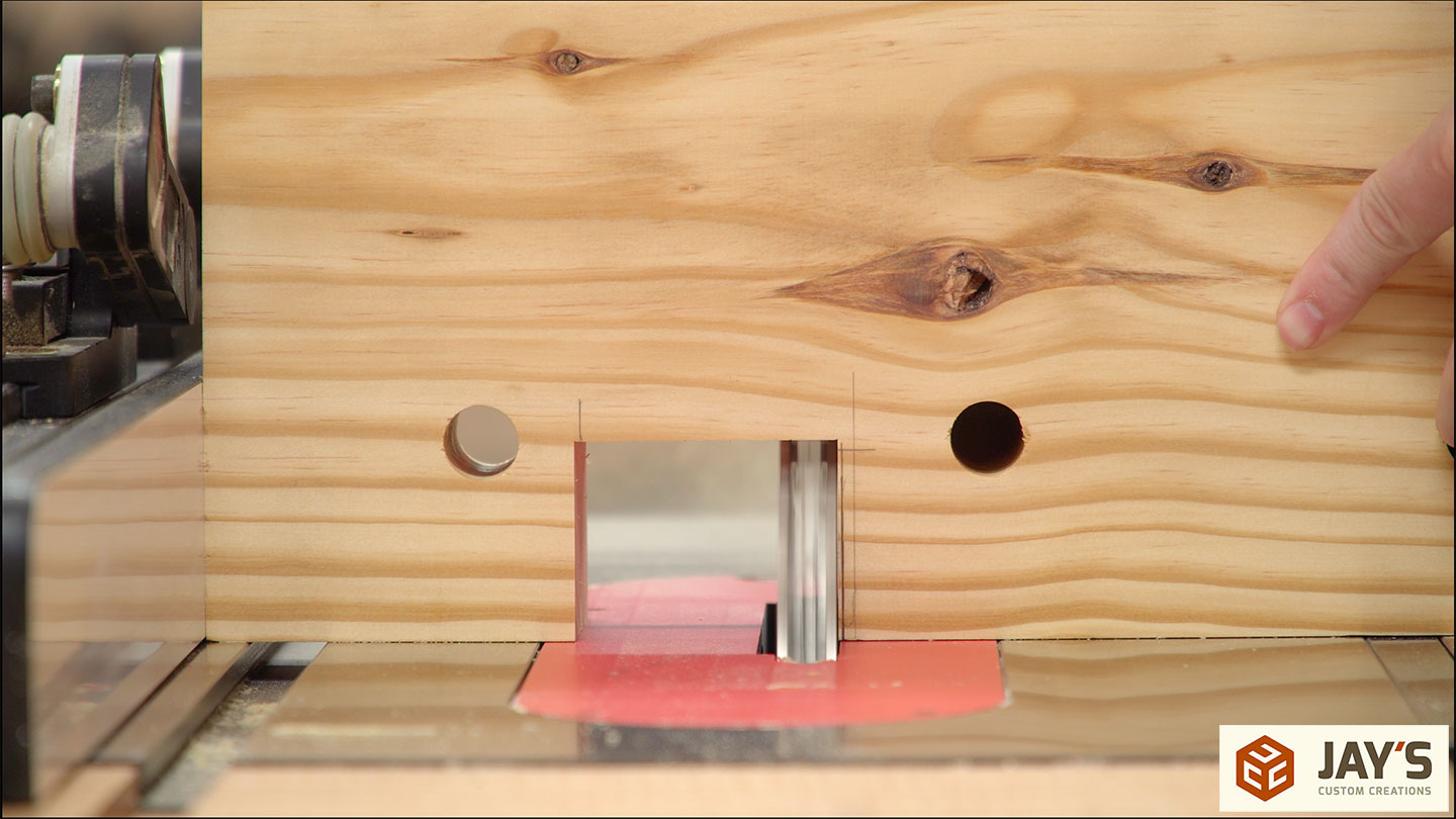
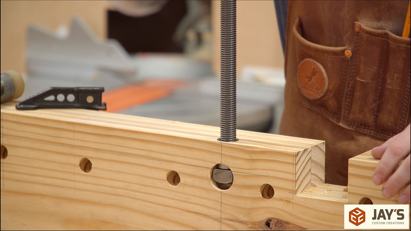
Here you can see how this will work. The square nut goes into the hole and the bushing will go into another hole in the front face.
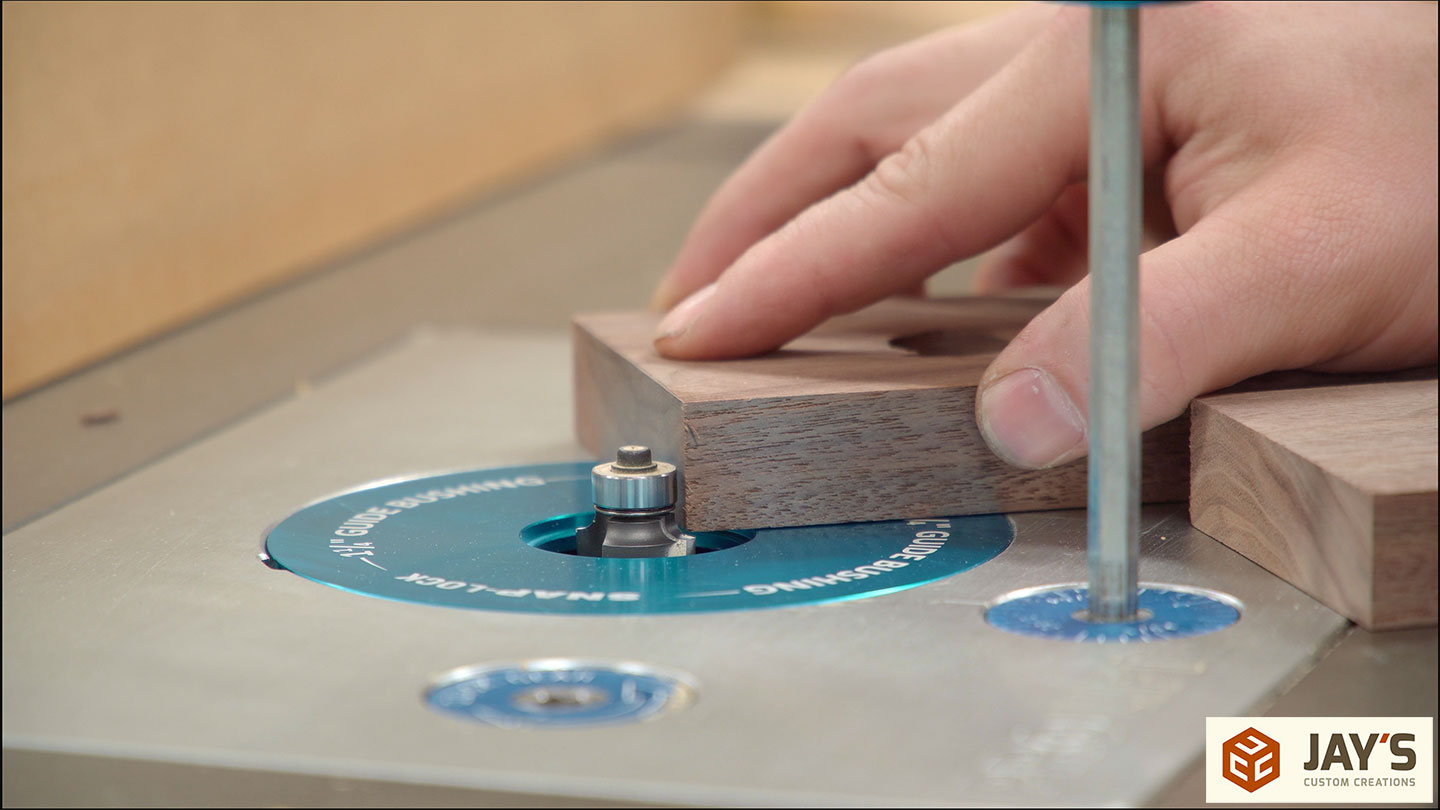
That hole is drilled first at the drill press and then followed up by hand with an overdrive bit and a bit extension.
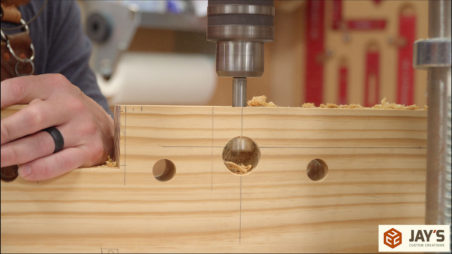

The threaded rod should pass through the bushing, engage the nut, and then go into the open space beyond without touching any pine. This ensures the smooth operation of the screw.
While the drill press is still set up the dog holes on the back face can be drilled. The final depth here is determined by the dogs and clamps you may use in them. Just make sure to not go deeper than the length of the dogs so the dogs don’t accidentally get stuck in the holes.
Finally, the extra piece can be glued to the bottom of the front edge. This just gives a little more material support to the stationary face of the vise. It’s also important to wait until after the nut mortises are drilled as it will partially cover the hole location.
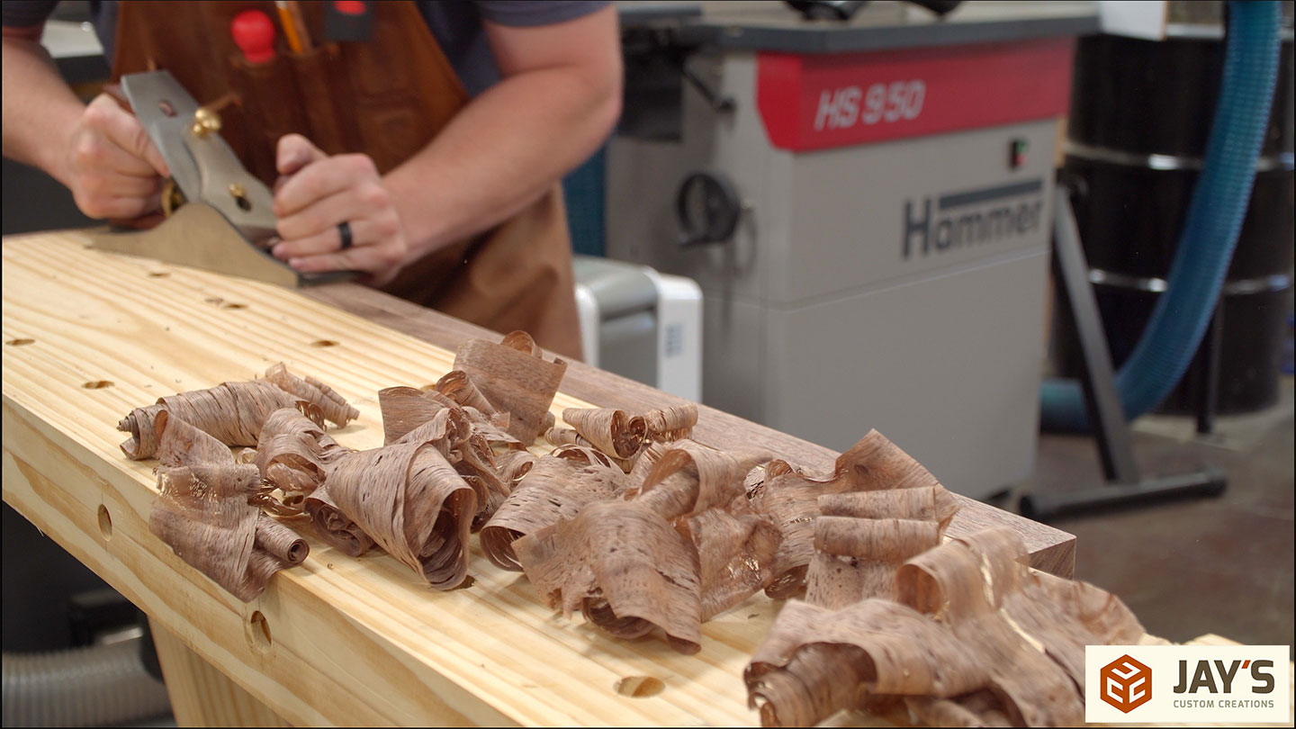
While that glue dried I milled some walnut for the vise and end stops and then took way too long of a lunch break.


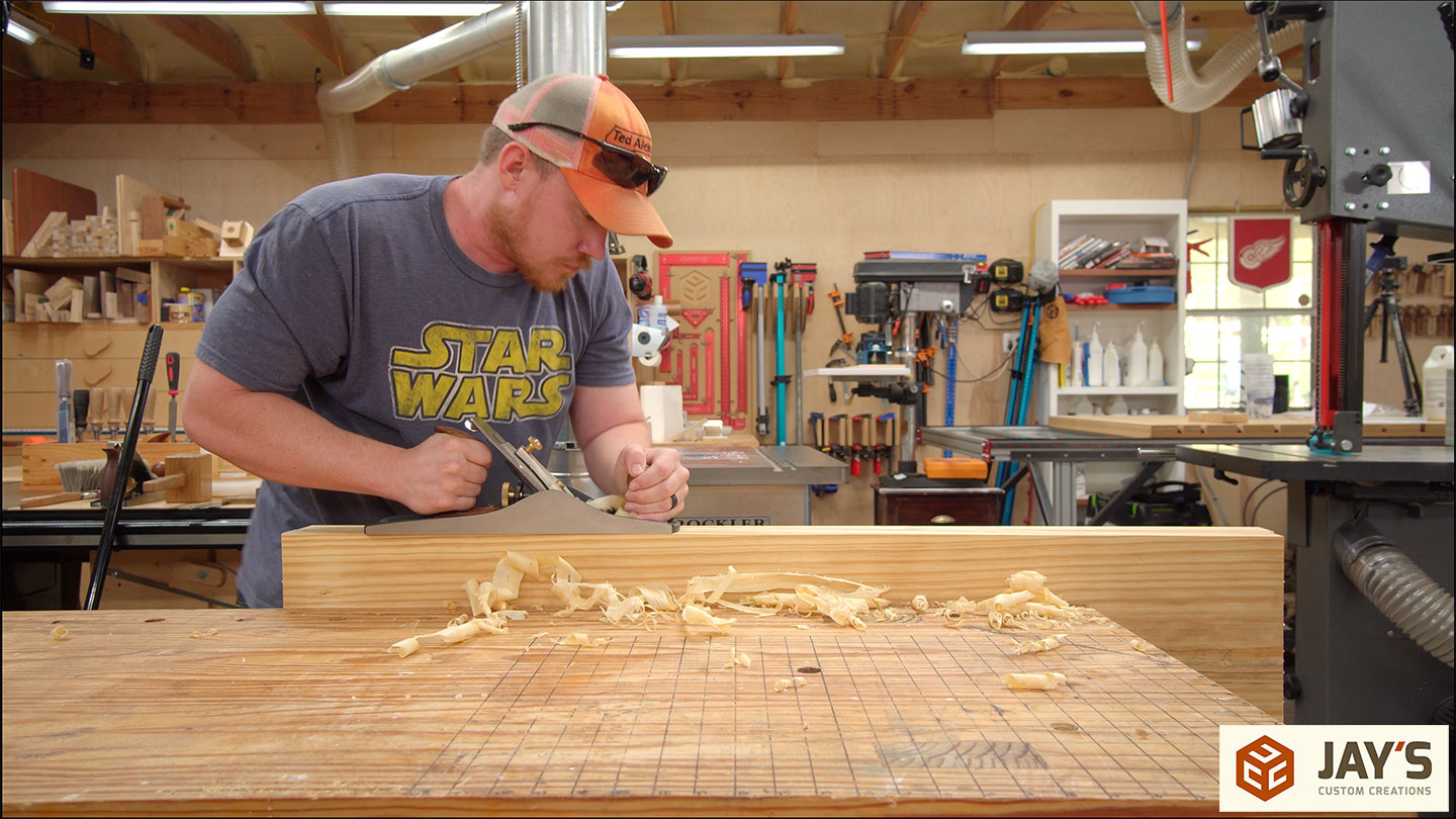
After lunch and possibly a nap in a hammock I flushed the built-up front face with a smoothing plane making sure to not modify the original front face as I already knew it was flat and square.

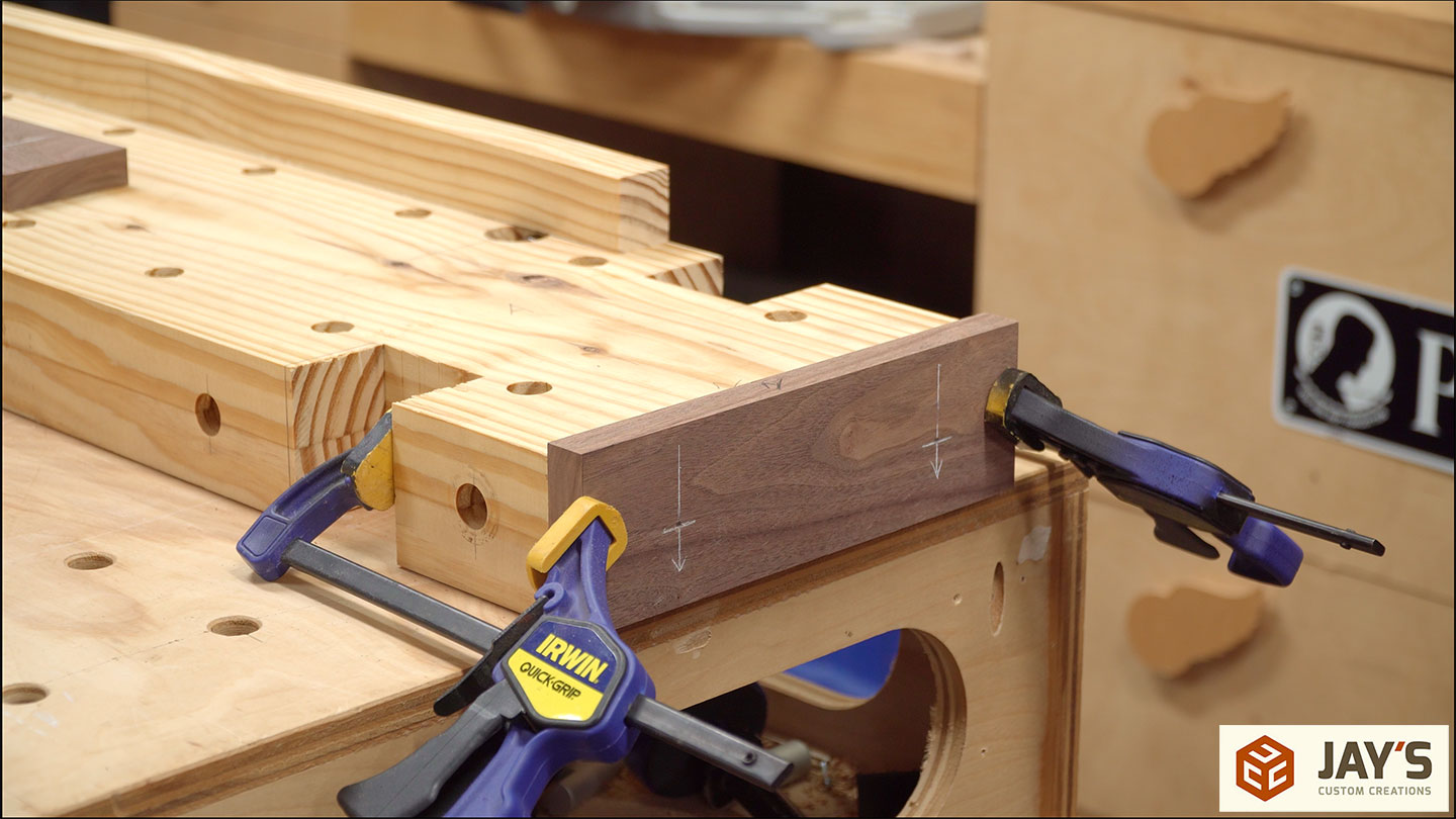
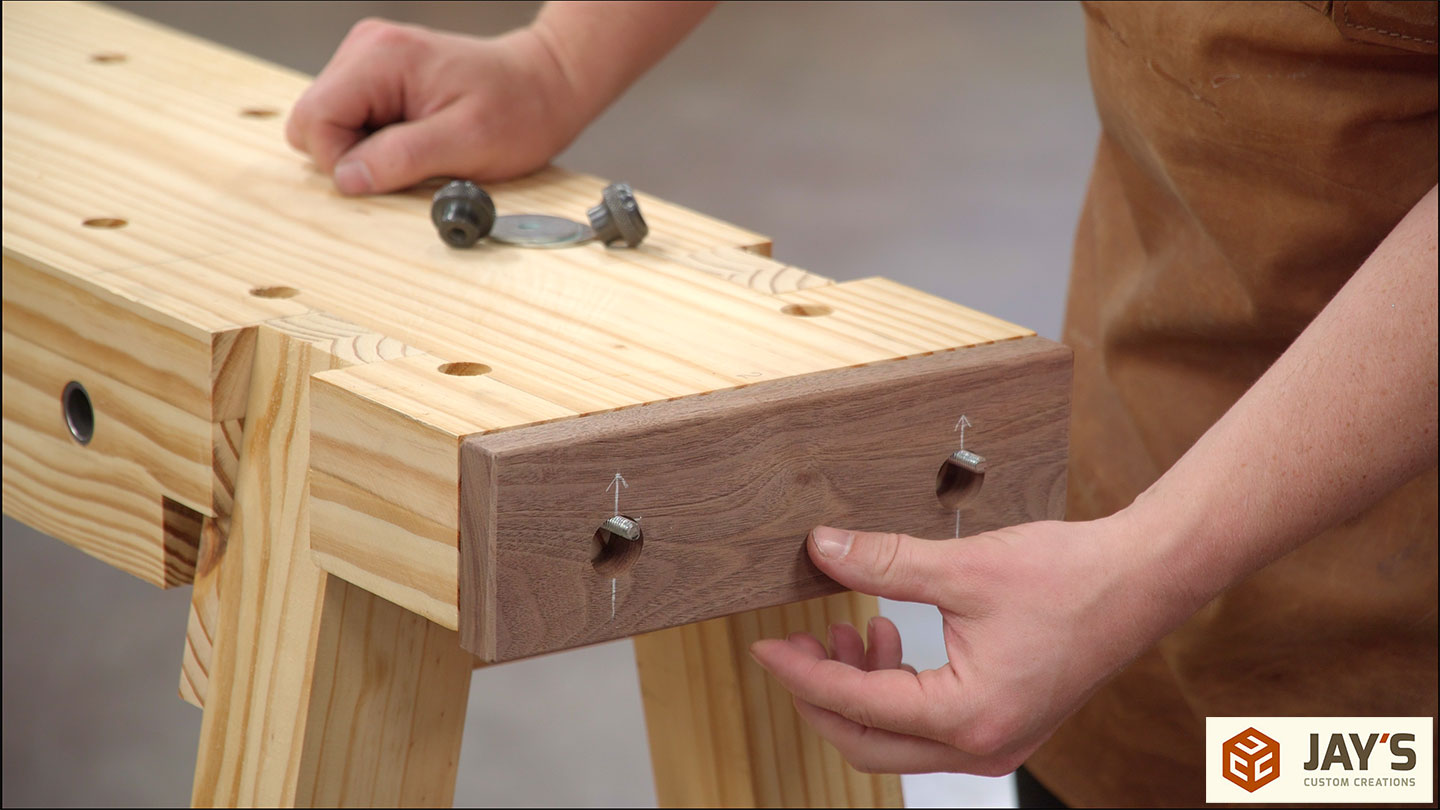
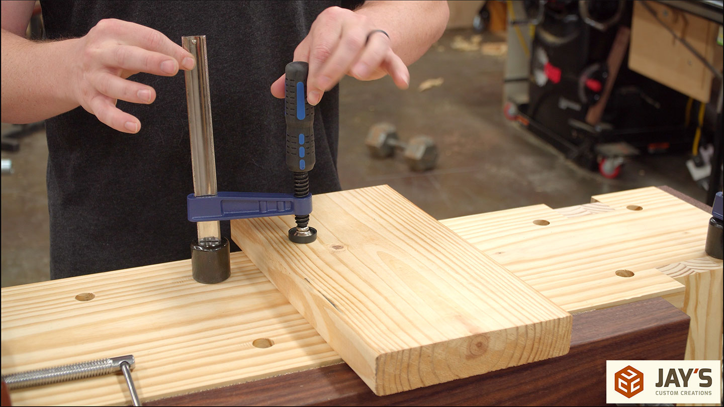
Here’s how the end stops attach. First, I made them slightly wider than the thickness of the top. With the top face down on the assembly table, they are clamped in place and a 3/16” hole is drilled through the walnut and into the pine.
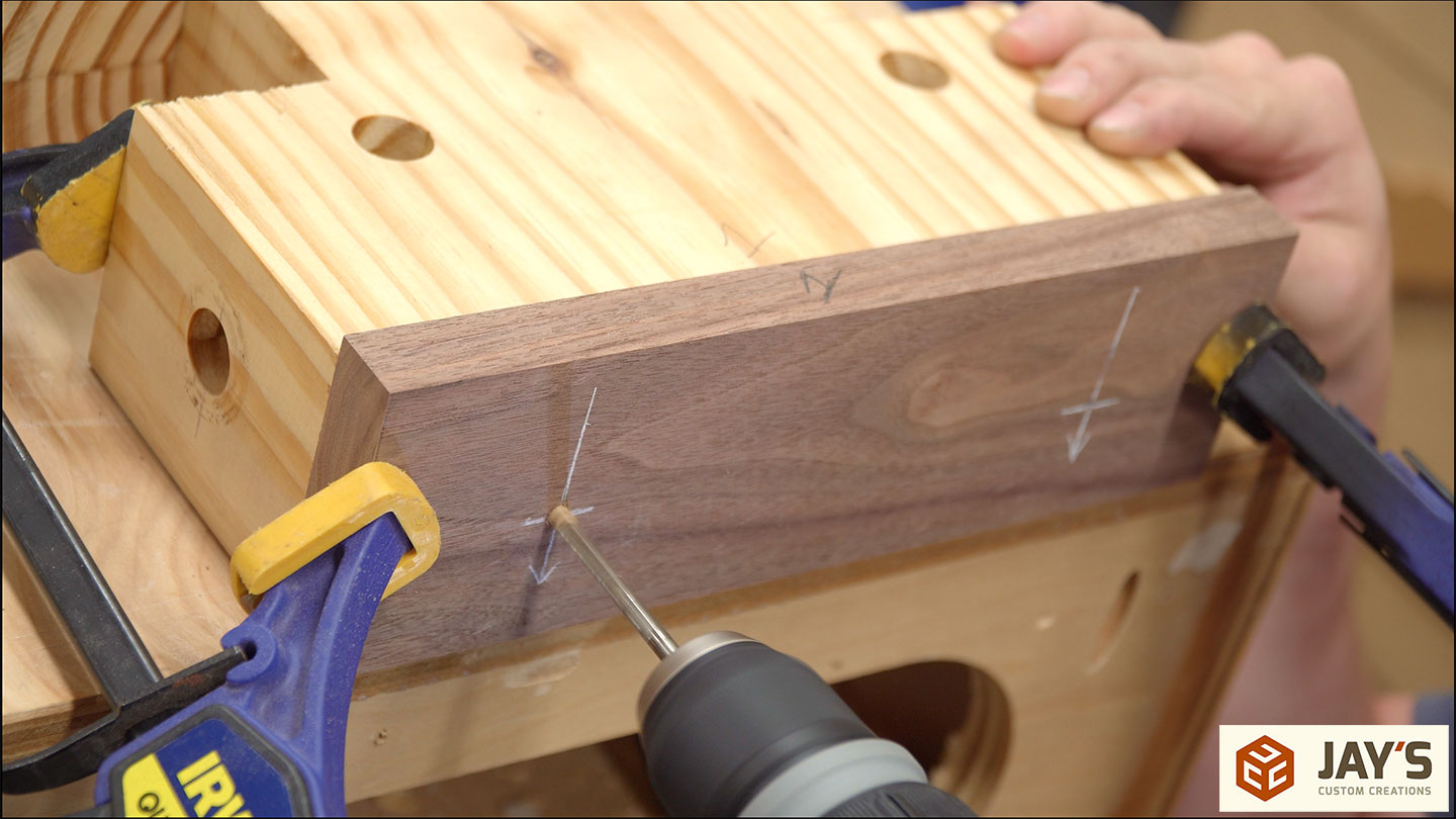
Then a 1/4-20 bolt is driven all the way through the hole in the pine to establish threads.
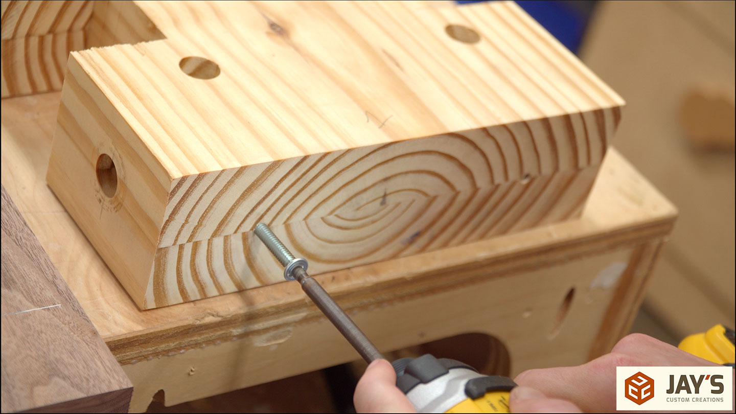
Then a little thick CA glue is put into the holes.
Then some 1/4-20 carriage bolts are installed.
While the CA glue sets up I took the end stops to the drill press. They get a 7/8” hole drilled offset from the first hole. The goal here is to make sure the top edge of both holes touch with the smaller hole being completely removed.
Now the heads of the carriage bolts are cut off and the end stops are installed. The 7/8” hole allows for 5/8” of vertical travel with a 1/4” carriage bolt. This method requires a larger fender washer but is much easier than cutting a slot.
By now the glued-up walnut for the front vise has had enough time in the clamps and can be milled to its final size.

The same storyboard is used to locate the screw holes which are then drilled at the drill press.
Here’s a step I did out of order. I should have waited until after the final fit of the end stops and front vise to add this 1/8” roundover. But I didn’t so learn from my wasted time.

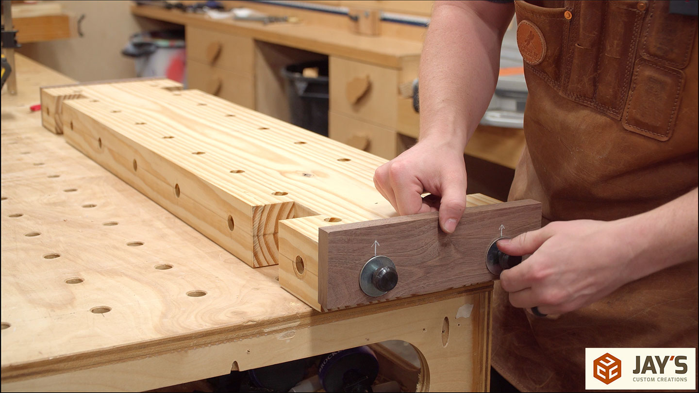
A matching angle is cut onto the bottom of the legs. This can be done at any time. Notice I had to use a spacer block to elevate the leg slightly. This is due to the lower stretcher being on the opposite side as the upper stretcher. It really doesn’t matter what side the lower stretchers are on but the top stretcher needs to be on the inside to avoid interfering with a dog hole.

To help seat the legs a little easier I used a file to ease the edges on the bottom side of the top.
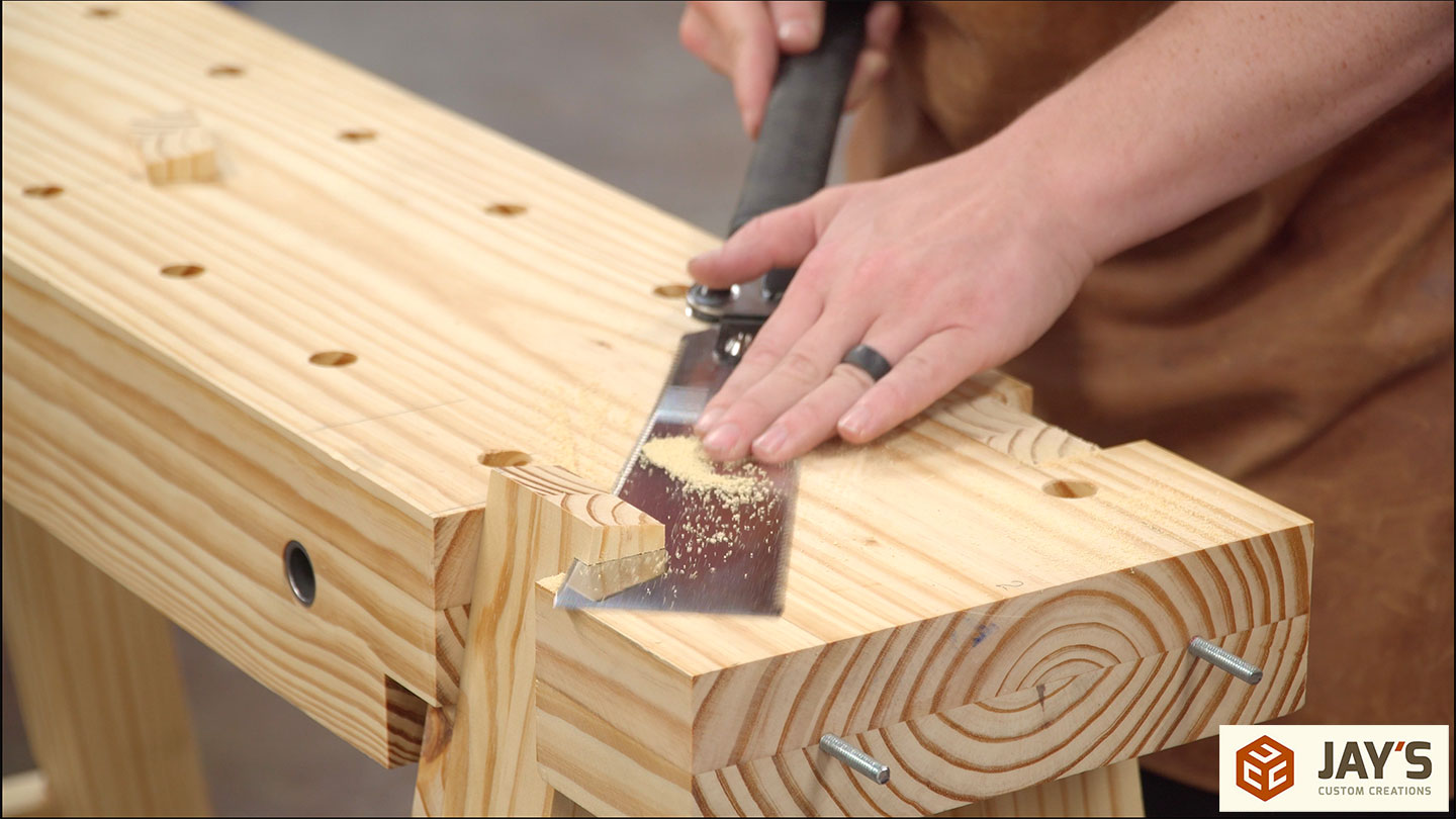
A flush trim saw is used to flush the legs up with the top.
Here you can better see how the holes work for the end stops. Again, I chose this route simply because it was easier than cutting slots. The same thing is achieved this way.
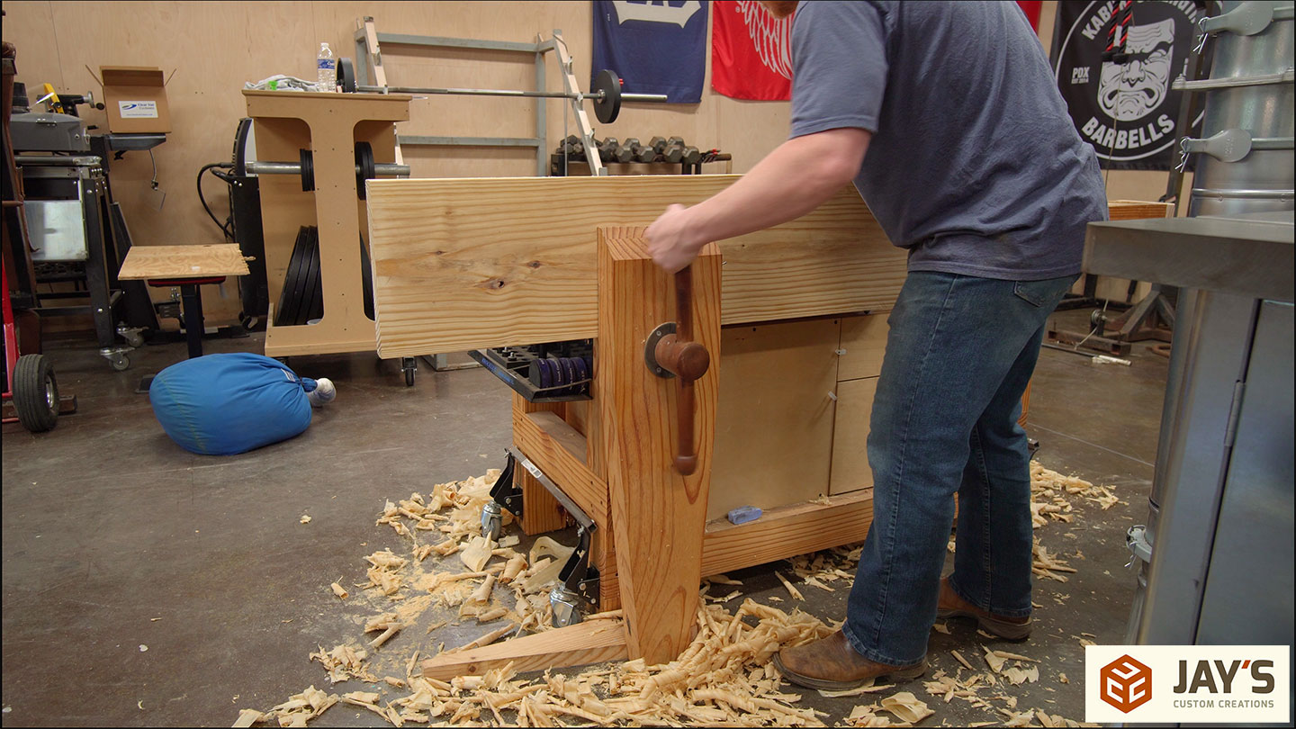
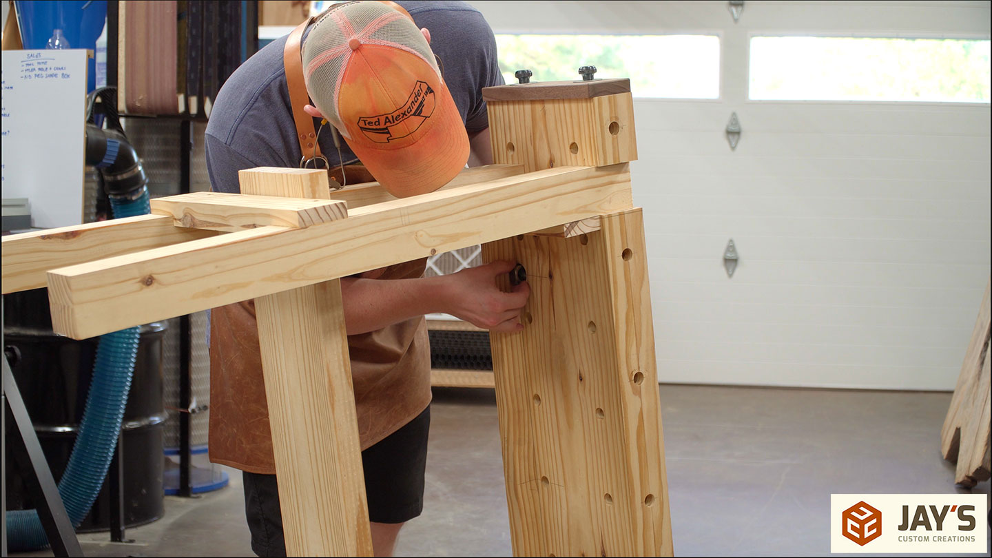
To install the front vise for the first time I put the work horse on its side so gravity wouldn’t be a hindrance. It turns out that it’s just as easy to install in its normal orientation.

The vise was intentionally cut taller than necessary so I could flush it up with a hand plane. I had to add a sandbag to the lower shelf to stop the work horse from moving and also adjust the linear clamp a little bit after this step.
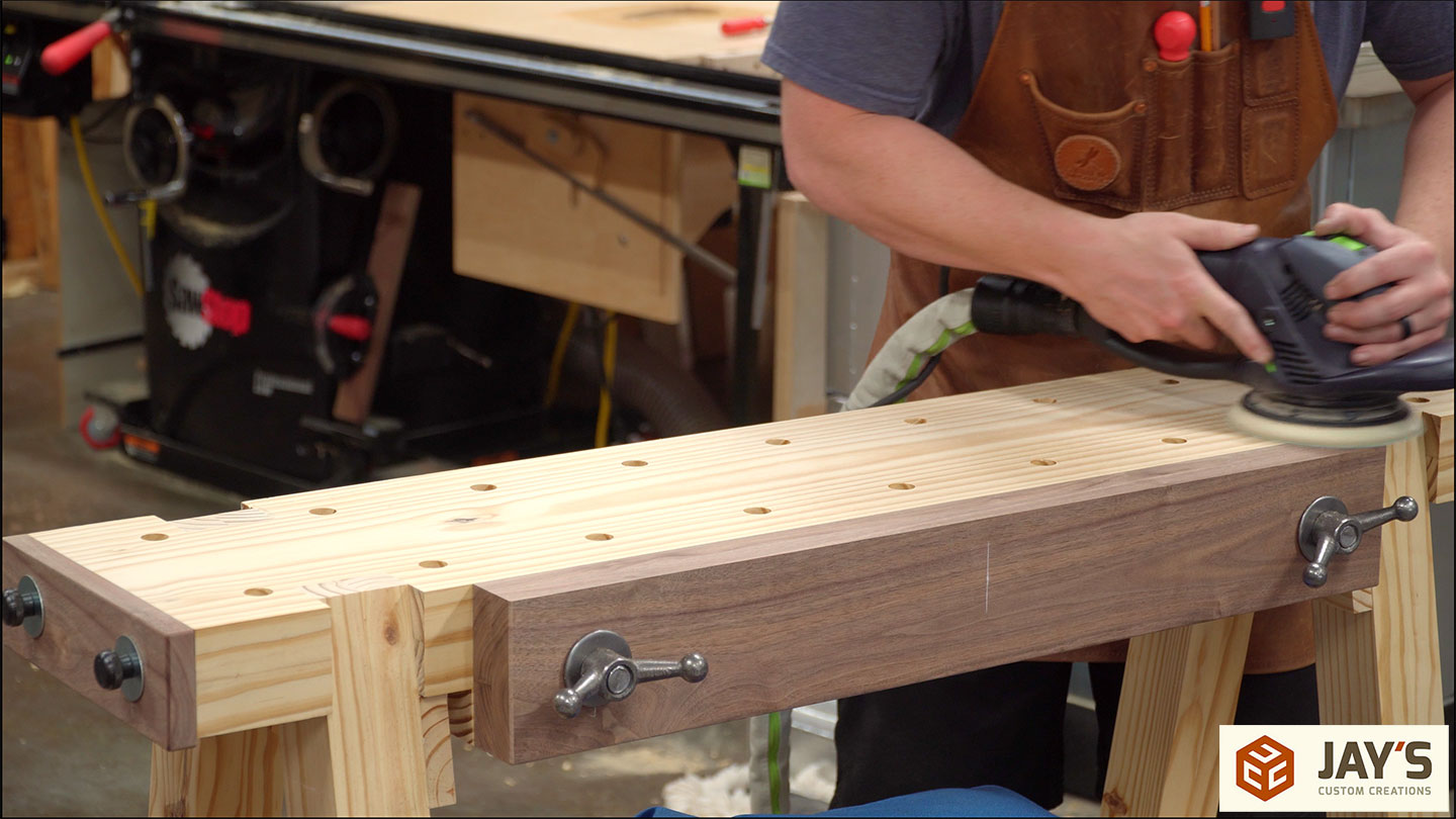
Finally, a little sanding to remove pencil lines.
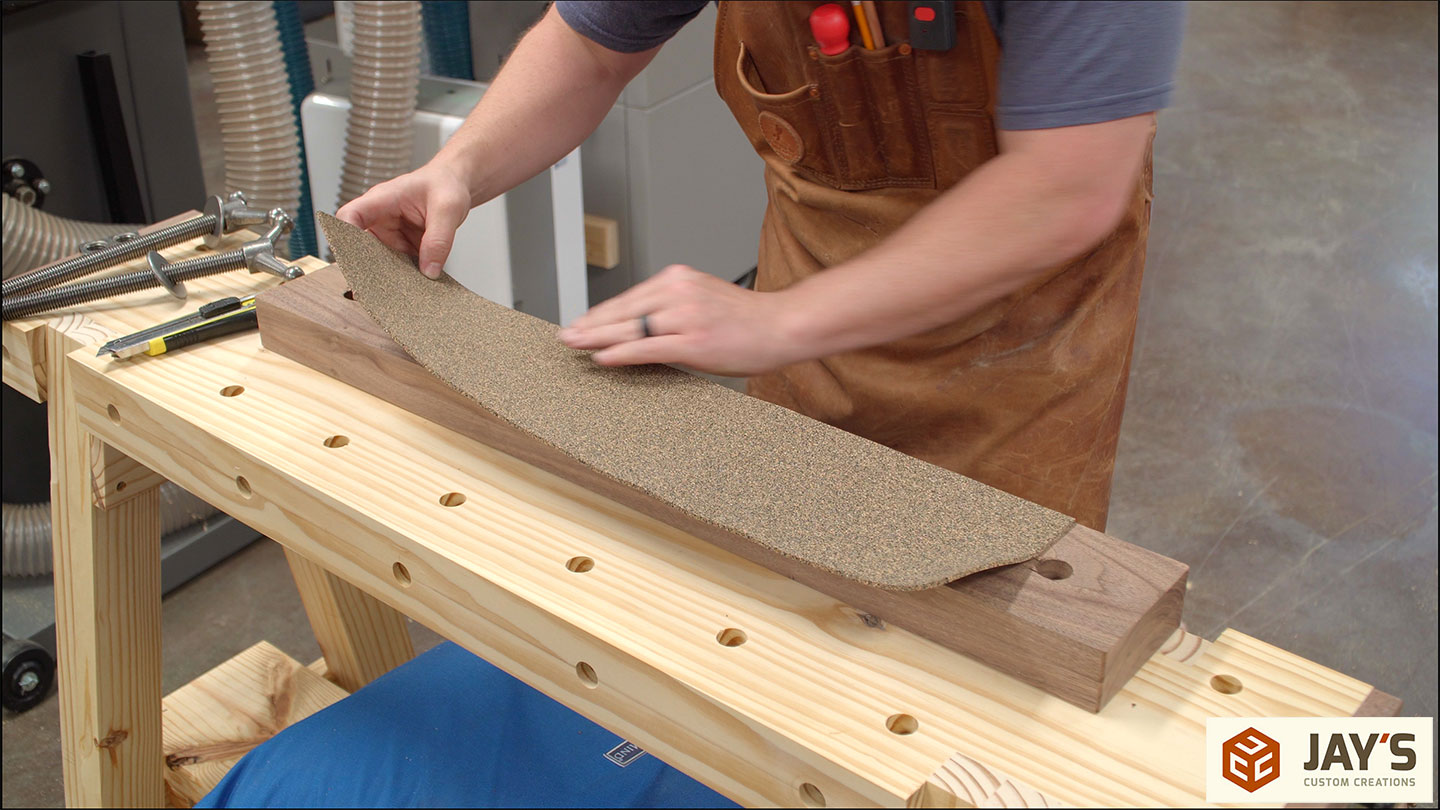
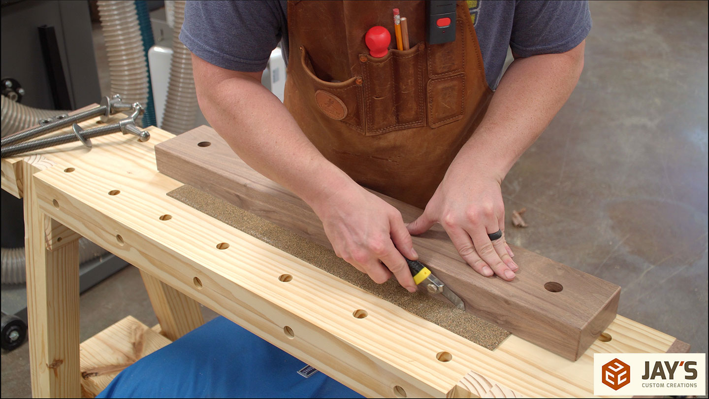
For added grip, some cork rubber is added to the vise jaw. Do not add this stuff to both sides of your vise as doing so will allow the work piece to wiggle in the vise as there will be too much cushion.
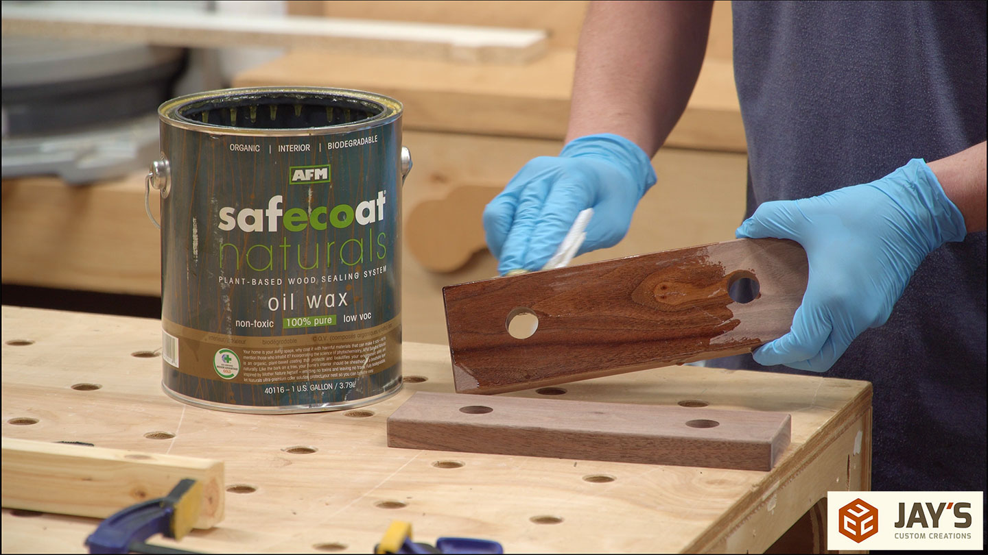
I used an oil wax finish to just the walnut pieces. I want to keep the pine free of finish for the maximum amount of friction when working with pieces.
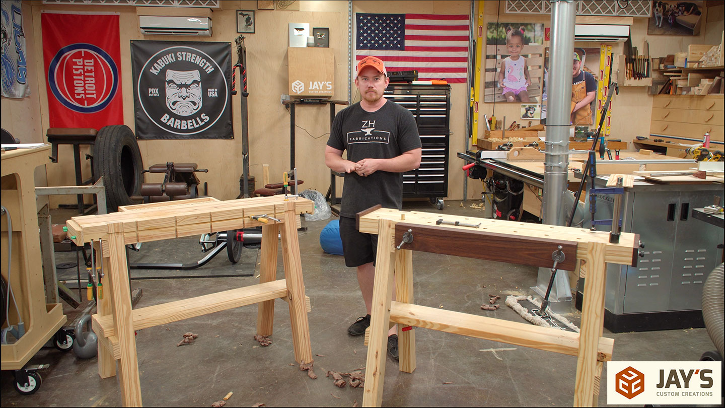
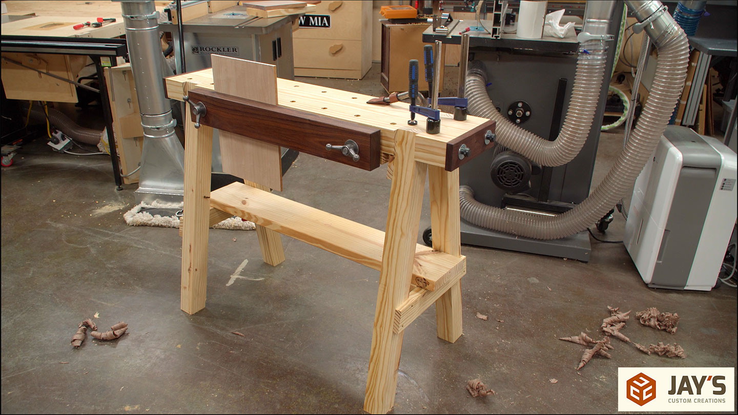
Here are some completed shots of the work horse. This traditional work horse is the exact same construction as the Matchfit work horse. So rather than making a completely new set of plans for this, I am including an addendum to those plans for the specifics for this work horse. Same material, same construction, different workholding options. If you’re interested in a set of plans I have them available here.


Nice, it’s weird that when I saw the first video, I immediately thought: “hey, but that’s a concept that would be real easy to adapt for traditional hand tools too!” and some weeks later, there you go ! Nice execution !
I loved the silly humorous start! Keep it up, that cracked me up!
Thanks for the feedback and thanks for watching, Kévin.
Very nice workhorses! I didn’t look at the link but another inexpensive twin screw vice source is a barbell shaft with nuts! I’ve built a couple Moxon vices using these and they work great! I had a good laugh and your descriptions of operations, “6.5 pound paperweight” LOL. Great job! You kept my attention throughout the vid! Thanks Jay! Keep up the good work!
Interesting. I’ve never heard of that. But this kit is much cheaper than any barbell or dumbbell that I can find.
Great job and an informative & amusing video. Many thanks for sharing!
Thank you very much for watching.
But did you verify with the other match fit guy if he’s working on a traditional workhorse first?
What are you talking about?
Is the fence on your bandsaw aftermarket? I’m looking for a new fence, as the one that came with my Rikon leaves a bit to be desired. Like actually being straight…
It’s the factory fence from Laguna. When resawing I have to put a clamp behind it on the back end to stop it from wandering. Typical of a T square style fence.
Like everyone else, I like the humor and how well you make the videos. I’m like you, hand tools sometimes, power tools most of the time. Great work Jay, as always.
Thanks for the feedback, Derryl. Much appreciated.
Naps are good anytime,Jay
This was fun, and inspiring to watch. I have little space, so the form of this one, including being collapsable makes a nice opportunity for hobbyists like me to participate without needing a big hunky bench. I have been looking to create a Moravian bench, but using power tools (just to irritate the purists and my skills are better there). It is a daunting task. Now I am thinking of a cross between this and the Moravian. Using pegs to hold the top, tusk tenons, etc. I don’t own planes yet, so getting the wood flat and square for the glue-ups d is still my nemesis. Any suggestions on first planes and sourcing wood almost square and flat would be nice. Also, if you don’t mind, what was your cost in effort (hours) and supplies (dollars)?
Amazing video, very nice job, thank you.
Jay…nice job..really enjoyed the video and love your style. You did such an amazing job filming and showing your process as well as providing sources for the hardware. So impressed that I felt that I had to buy the plans to support the channel. Thank you..