It is the season of gift giving and therefore gift making. I made a total of 16 cutting boards to give to local friends and family. All of the cutting boards were long grain boards. I’ve got an upcoming inlay end grain cutting board that I want to try but for now, and for these, I stuck to long grain boards. All of them are hickory.
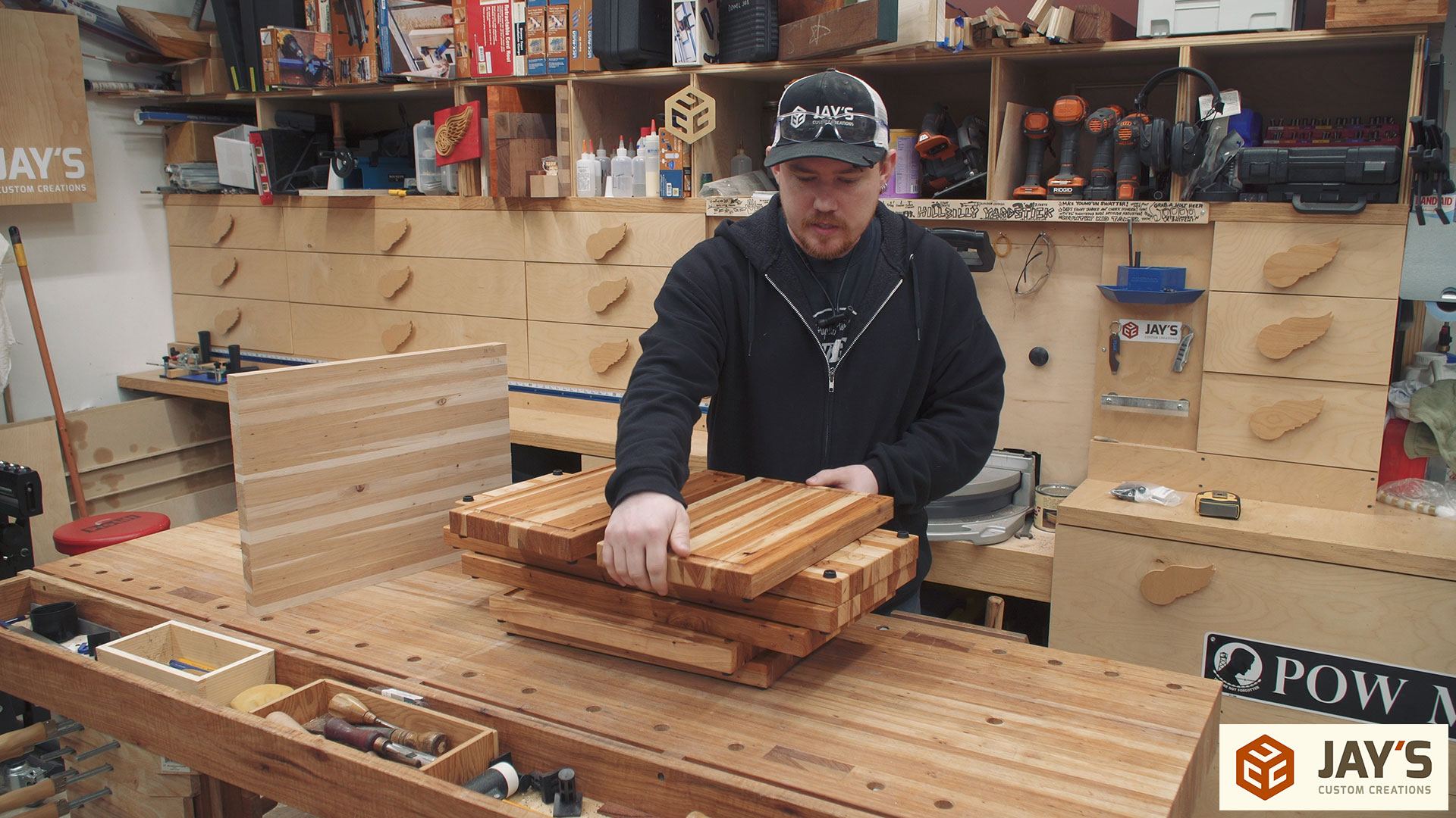
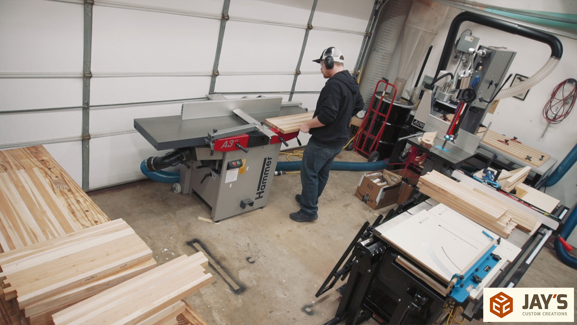
These cutting boards started back in the summer time. I think it was June when I originally glued these together. I had a stack of hickory offcuts that were too long for the burn pile but too short to stack on the lumber rack. A friend of mine and I took a day to skip plane and rip everything to a set width that would eventually be the thickness. Then we glued similar length pieces together to get as many cutting board blanks as we could. My last planer could cut these but the rollers just didn’t have any grip on smooth hickory so I set them aside for several months. With the recent jointer/planer upgrade in the shop I was able to get all of these flat and square on all sides and ready to personalize.
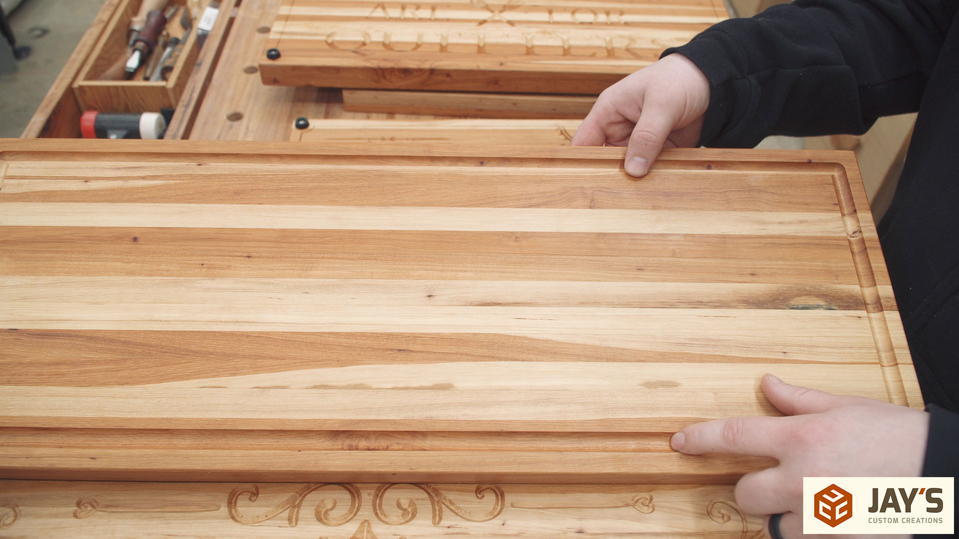
As I said, all of these cutting boards are made from offcuts. Wood that wasn’t used in a project for one reason or another. That means the boards are not free of defects such as knots and holes. I knew this when gluing everything together so we took the time to make sure all of the bad areas were on the same side. Personalizations would be made on the bad side to prevent it from being used with food. The good side got a juice groove. After experimenting with a few different locations and depths I settled on the center of the juice groove being .75” in from the edge, .2” deep, and cut with a .5” round nose bit.
The bottom of each got personalized. This gave me several opportunities to make changes and figure out what I did an did not like. On this board I used a 90 degree V bit that had a flat bottom and no point. For larger areas like the center design it worked great. For smaller detailed items like the corners it didn’t work good at all. This is due to the profile of the bit. Much greater detail would have been achieved if I used a 90 degree V bit with a true point. And even more detail/depth would have been achieved if I used a 60 degree V bit with a true point. Lesson learned.
The flat bottom V bit that I used isn’t a bad bit though. Just not ideal in this situation. The flat bottom of the bit is good for cuts where a specific flat depth is desired. The bit can be used to clean out the flat depth waste area without the need to switch to an end mill for a waste clearance toolpath if the area isn’t too large.
You can also see that the rose image on the top is cut pretty deep. This is because I did not specify a flat depth in the toolpath creation and therefore the depth of each area is determined by the bit plunging deep enough to cut the entire vector area with the bit touching both sides. For example, if a 1/4” wide vector is cut with a true V carve profile a .5” wide 90 degree bit will plunge .125” deep so that it will cover the entire area in one pass. If the vector is wider than the bit it will make multiple clearance passes to simulate a wider bit.
With this board I also realized having some kind of decoration near the corners made it much easier to eyeball the placement of the feet.
On this next board I used a smaller .25” diameter V bit with a true point to make a full depth V carve. I wanted to see what the cut would look like when the vector width is greater than the diameter of the bit such as with the spoon. It cut the spoon area in two passes and left a tiny ridge between them. This could be from various different things such as the work piece wiggling slightly as the bit changes direction, the bit deflecting too much if it’s cutting too aggressive and sticking out of the collet too far, or even the bit being dull and not cutting as it should.
On this board I also put a frame .5” in from the perimeter for the sole purpose of using the corners as feet locations. I liked how this made the feet placement foolproof. This cut was a single rectangle vector with a profile cut set at .04” deep and cut with the same V bit that was used for the design. The border cut was a little shallow for my liking with this one. When exporting the toolpaths it’s best, generally speaking, to merge all toolpaths with the same bit to reduce unnecessary time of manually starting the next toolpath.

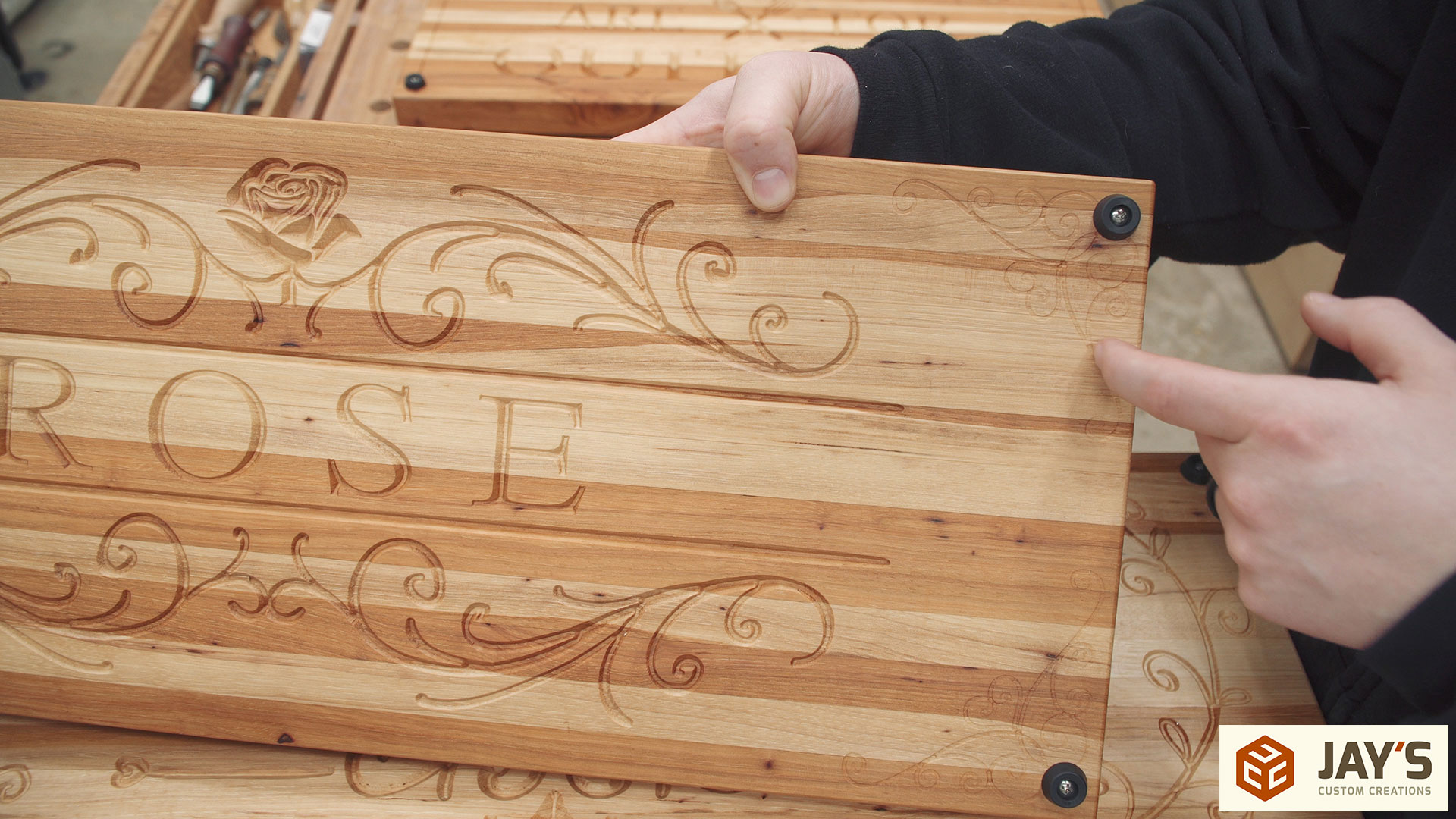
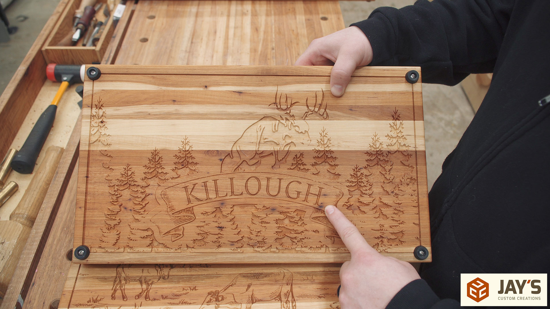
I wanted to try something with a LOT of detail and came up with this next design. I combined a few vectors for this one. The trees in the background are all one vector. The name banner is stacked on top. The name was created with the text tool and then placed along an arc matching the radius of the banner. The banner vector was offset and subtracted from the trees to give visual separation from the banner and the trees. And the deer was added on top and a smaller banner offset was subtracted from the deer to give visual separation there.
The entire design of this board was carved with a single V carve toolpath with a flat bottom set to around .08”. A .25” end mill was used as a flat bottom bulk waste removal path (automatically generated with the V carve toolpath)
I also used a .5” perimeter offset profile for the frame but noticed a mistake there. On the left side the tree is cut out resulting in a flat bottom for that tree. The V bit edge terminates with the perimeter profile vector. Then the border is cut with the same bit but I had it set to cut on center with the perimeter profile vector. The result is two edges of that tree not lining up. This made me realize that I should have set the border toolpath to cut with the same V bit but cut inside the vector and not on the vector.
On this board I also didn’t like how the lower left corner of the design was cut out and completely missing under the foot. It doesn’t affect the placement or use of the foot but there is a section missing under the foot and I just didn’t like it.
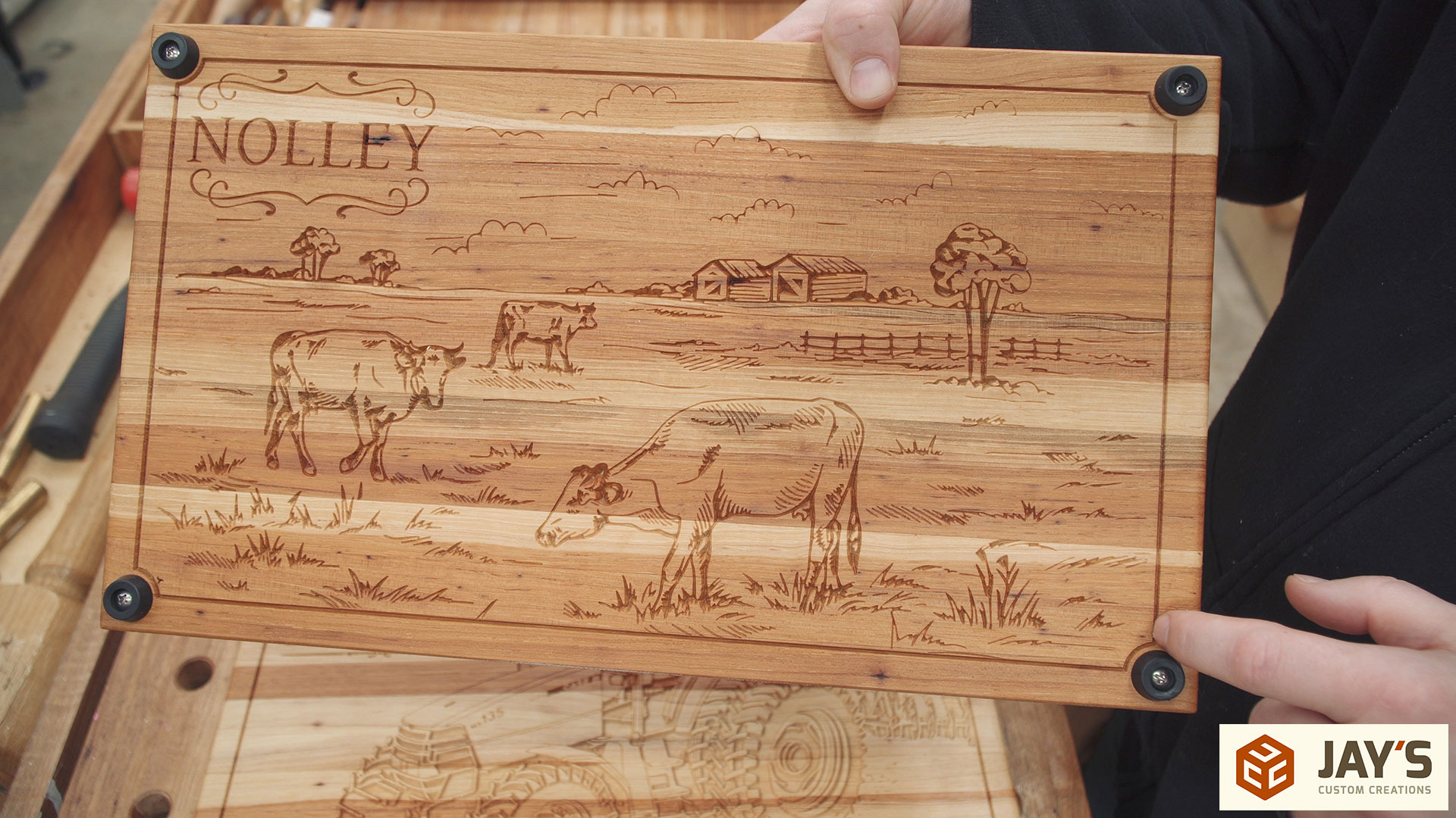
For the next design I used a true V carve profile with a 60 degree bit. Nothing special about the design. Just personalized for the recipient. I did experiment with the border though. For this one I made the border as normal and then added .75” diameter circles to the corners, used the interactive trim tool to remove ¾ of the circle as well as the corner of the rectangle. I also added .125” circles snapped to the larger diameter circle’s center. These smaller circles are exactly centered where the rectangle corners were at and are just deep enough to precisely locate the feet. I really like how the border no longer goes under the feet and better separates the feet and the design.
Around this point I also determined that I like the steeper wall angles of a 60 degree V bit compared to a 90 degree V bit.
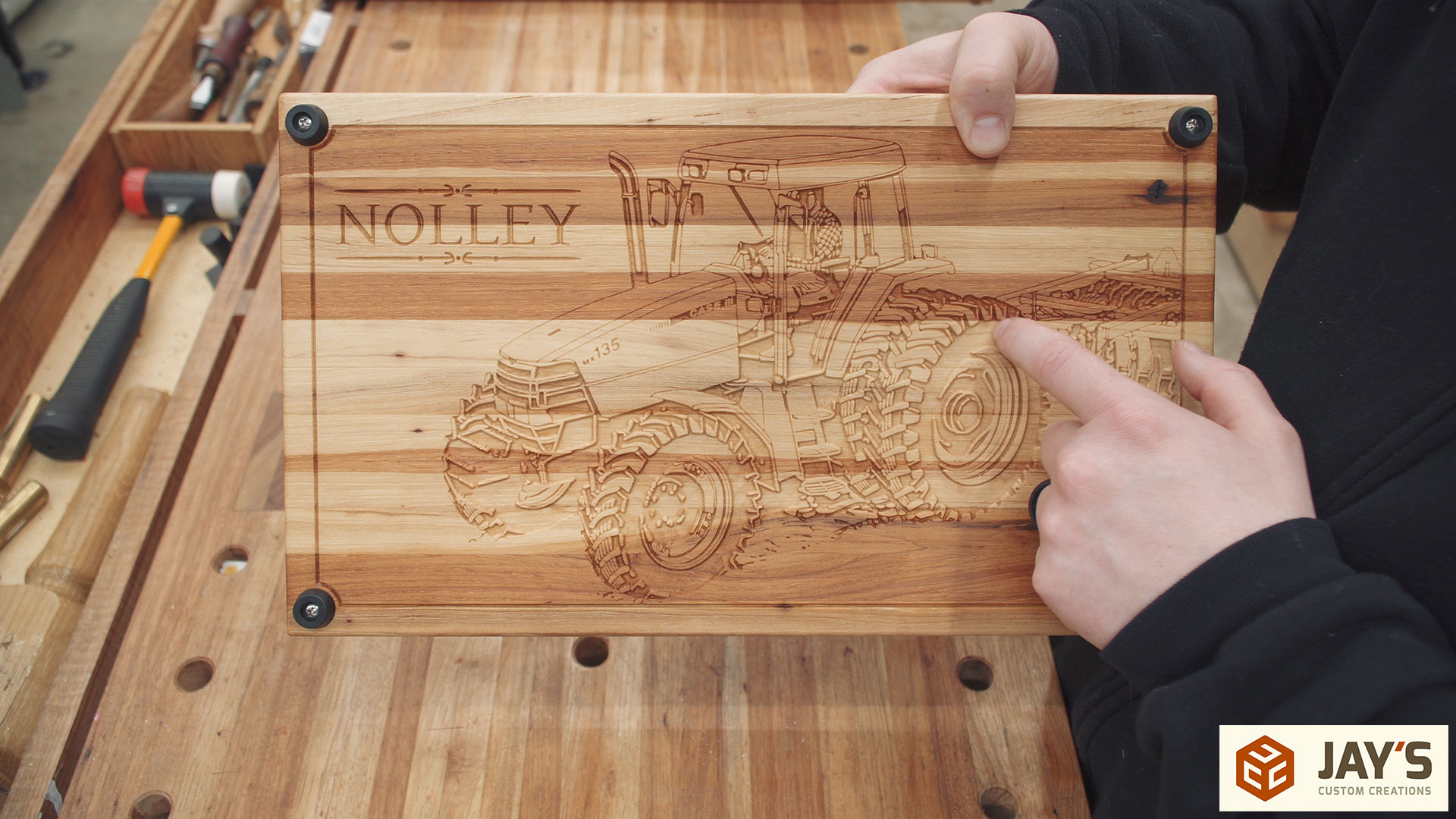
This design had a few larger vectors. Mainly in the tires. If a true V carve toolpath was used the bit would go unnecessarily deep with this design. I specified a flat depth of .05” and used the same 60 degree V bit I liked previously. The 90 degree bit really shows off the detail in busy areas like the drivers shirt and the tires. Again, I like the border corners.
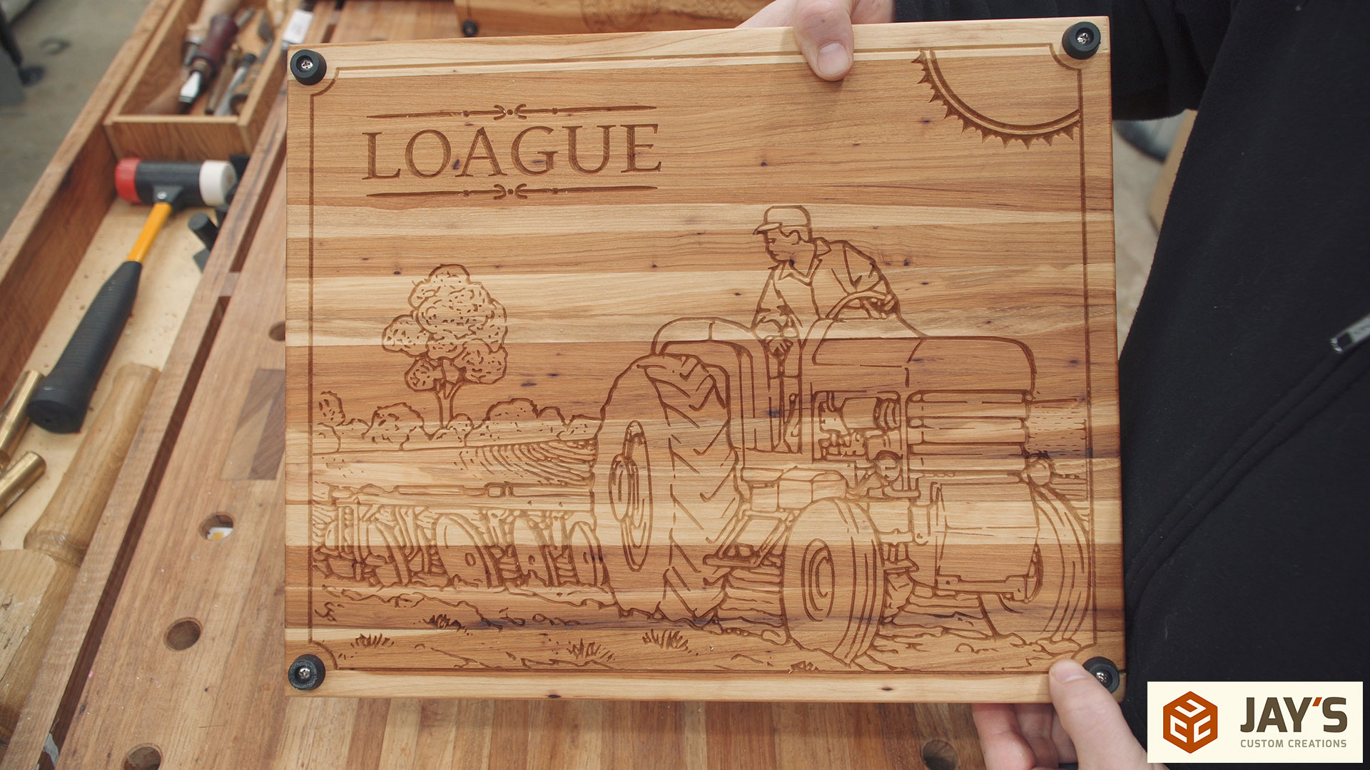
This last board was a true V carve. No changes in the design settings but I did change the feet corner radius slightly. I think I went with either a 1” or a .875” diameter and I don’t like it as much. To me there is too much separation between the feet and the border.
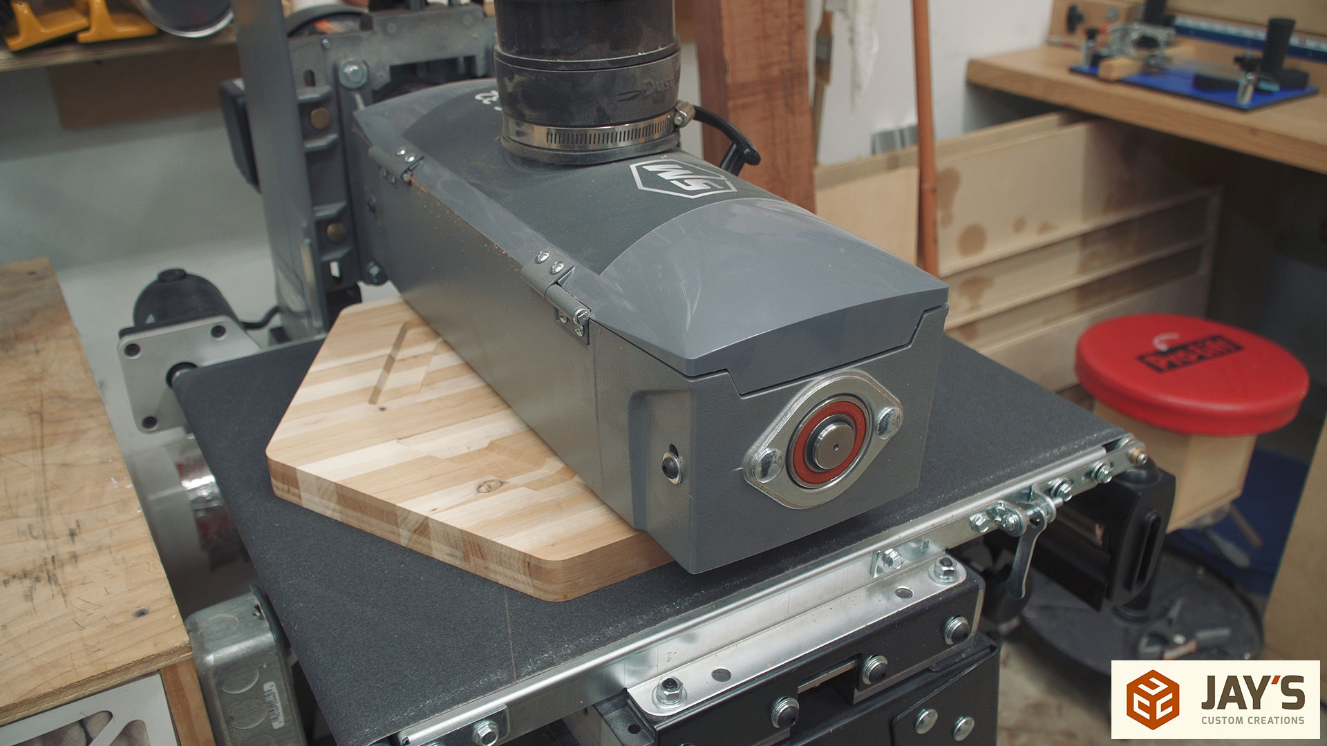
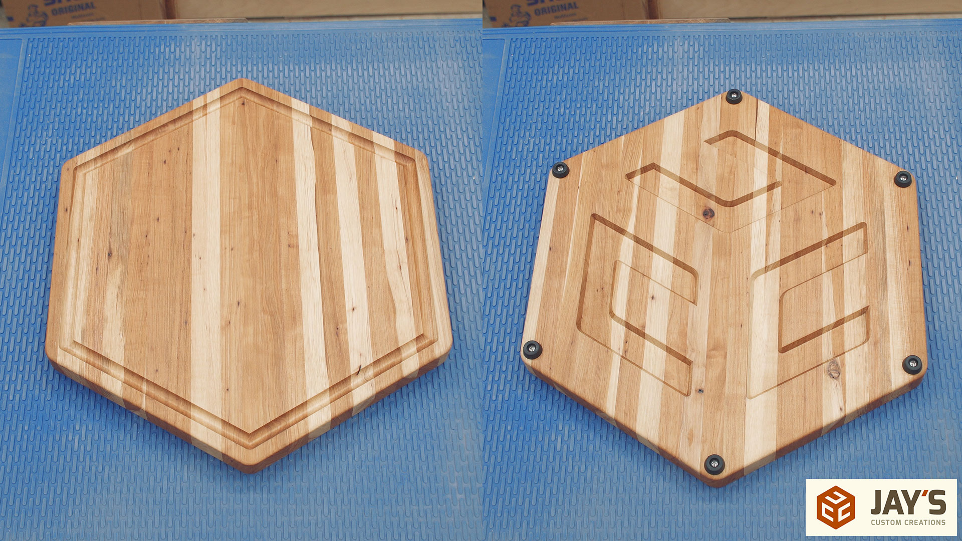
The rest of this article will be on personalizing the last (I hope) cutting board before Christmas. This board will feature the icon in my logo. I won’t go into detail on setting up all of the toolpaths and what I did exactly on the computer in this article. Everything is described in detail in the video. But to sum up the process, I imported, scaled, and centered the icon on the job sheet sized to the specs of the last cutting board blank. I offset the icon perimeter in to locate the feet placement and another offset for the juice groove. Then set the feet placement and the icon center as a V carve toolpath with a flat bottom. Made a juice groove toolpath. And finally a perimeter toolpath to cut half way through the board.
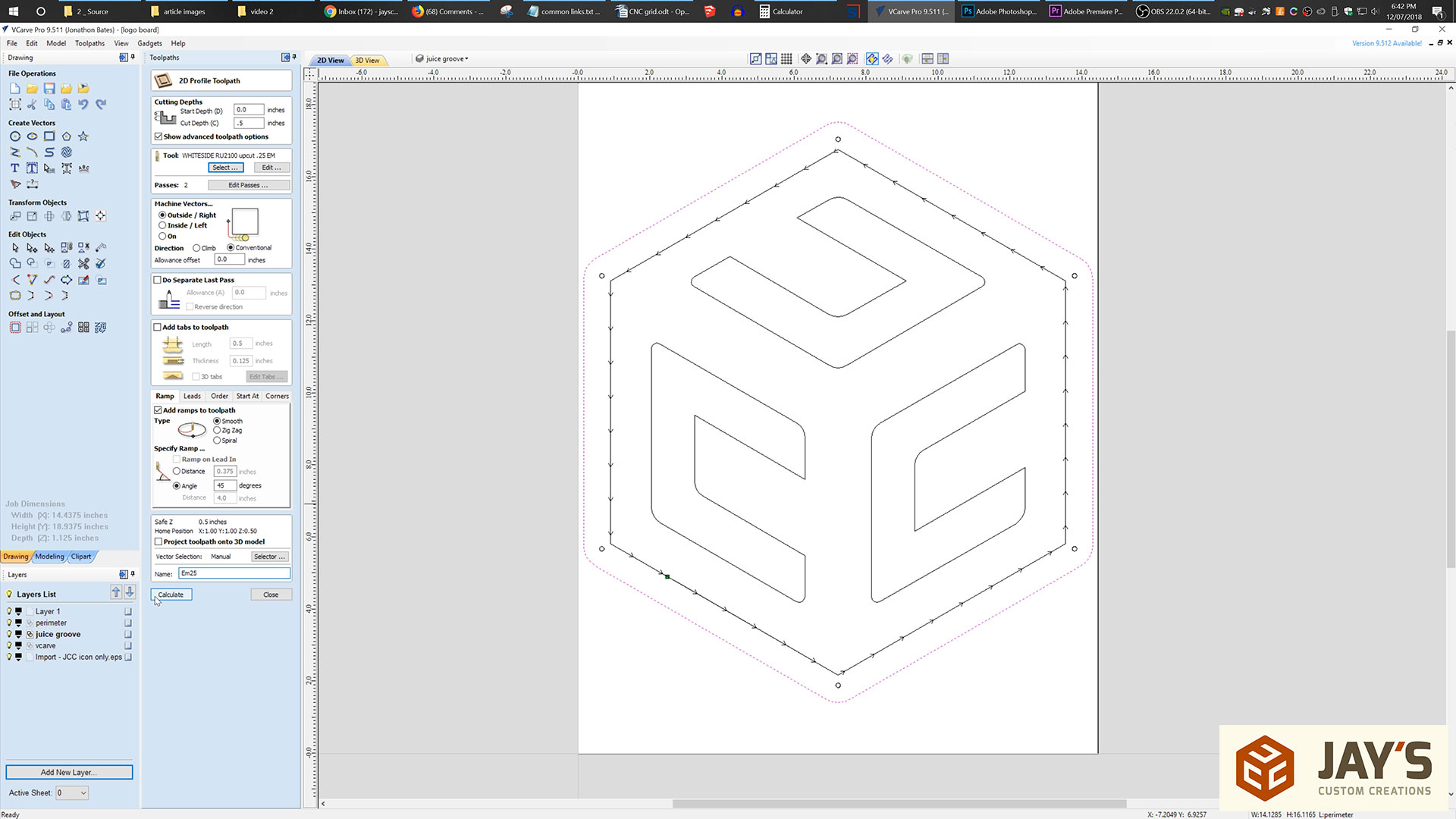
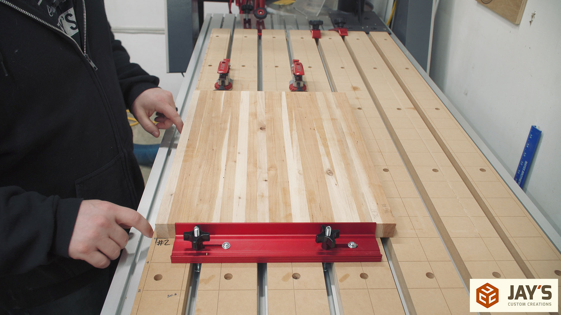
Because I’m cutting on both sides of the board it’s important to be able to have a repeatable setup for positioning the material. I used a stop block along my X axis and lined up the board with the Y axis engraved into my wasteboard (see CNC wasteboard grid article). When flipping the board all I need to do is make sure to be in contact with the stop block and lined up with the same Y axis line.
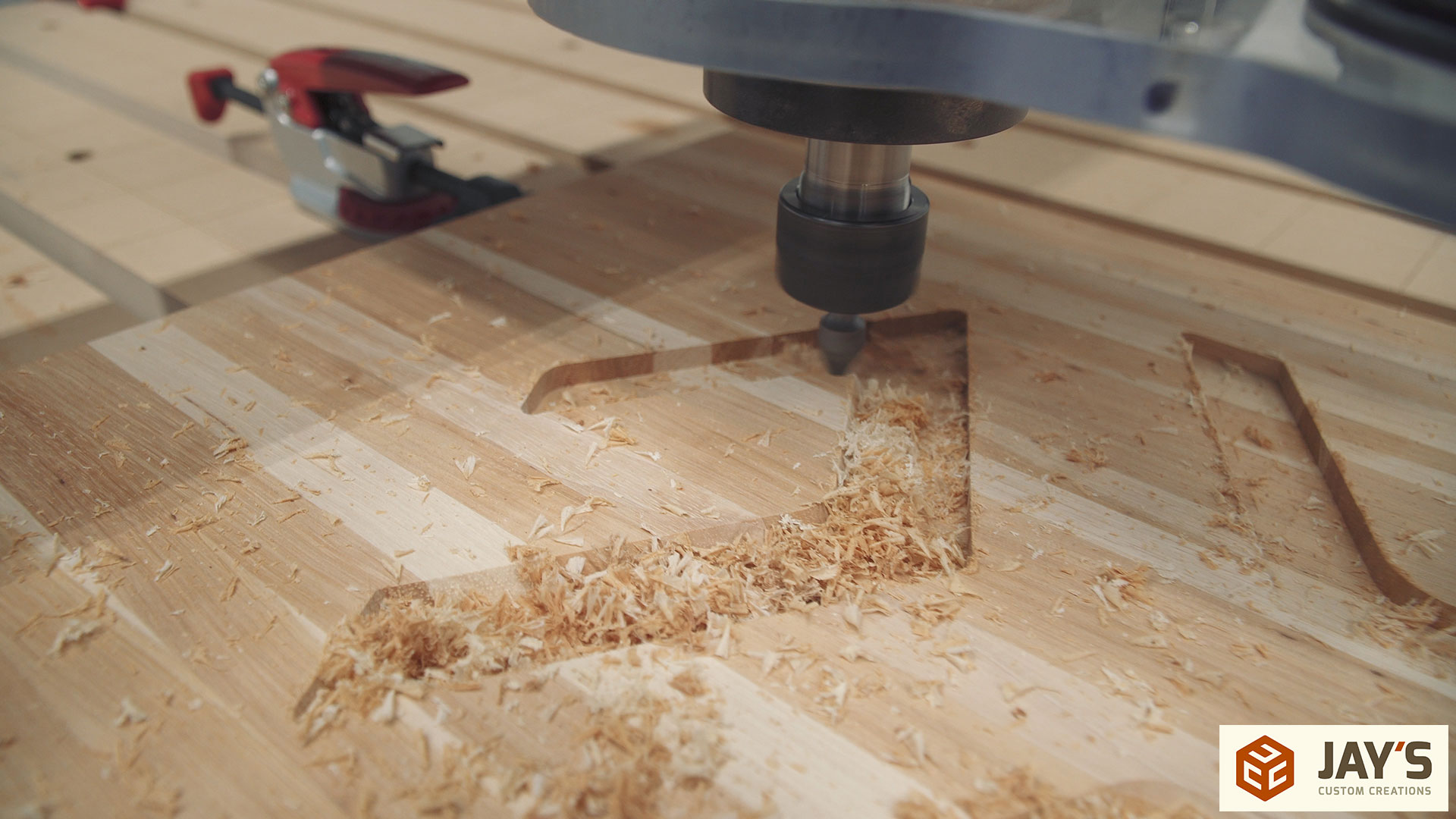
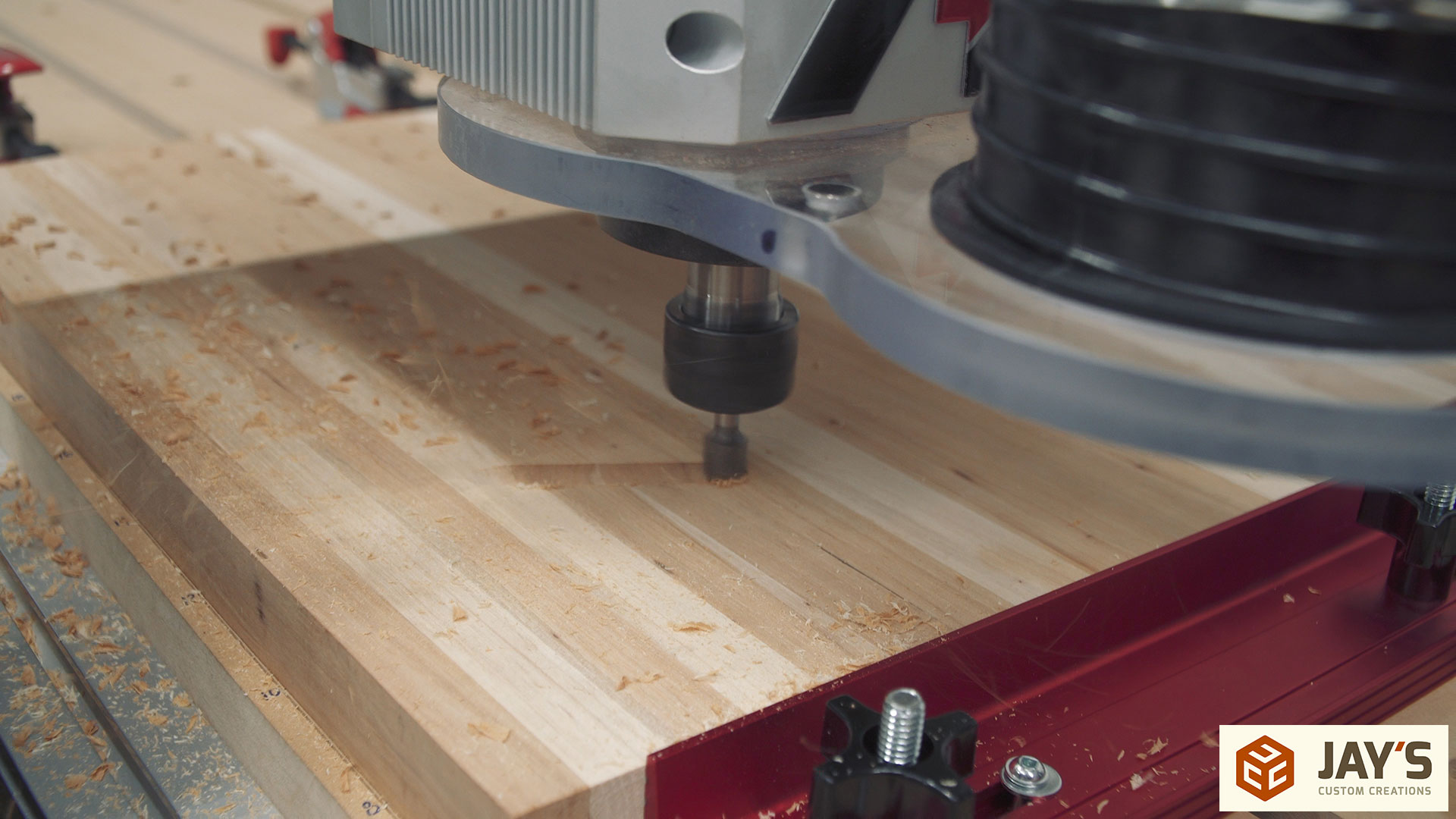
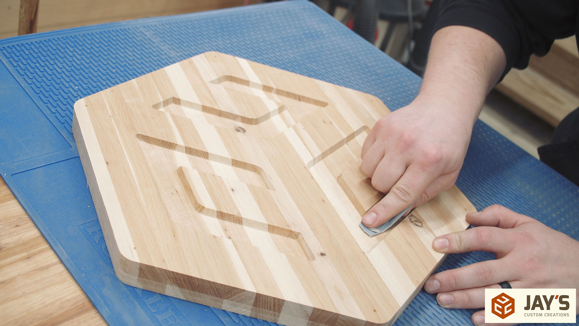
First a 1/4” end mill is used to remove the bulk of the V carve area.
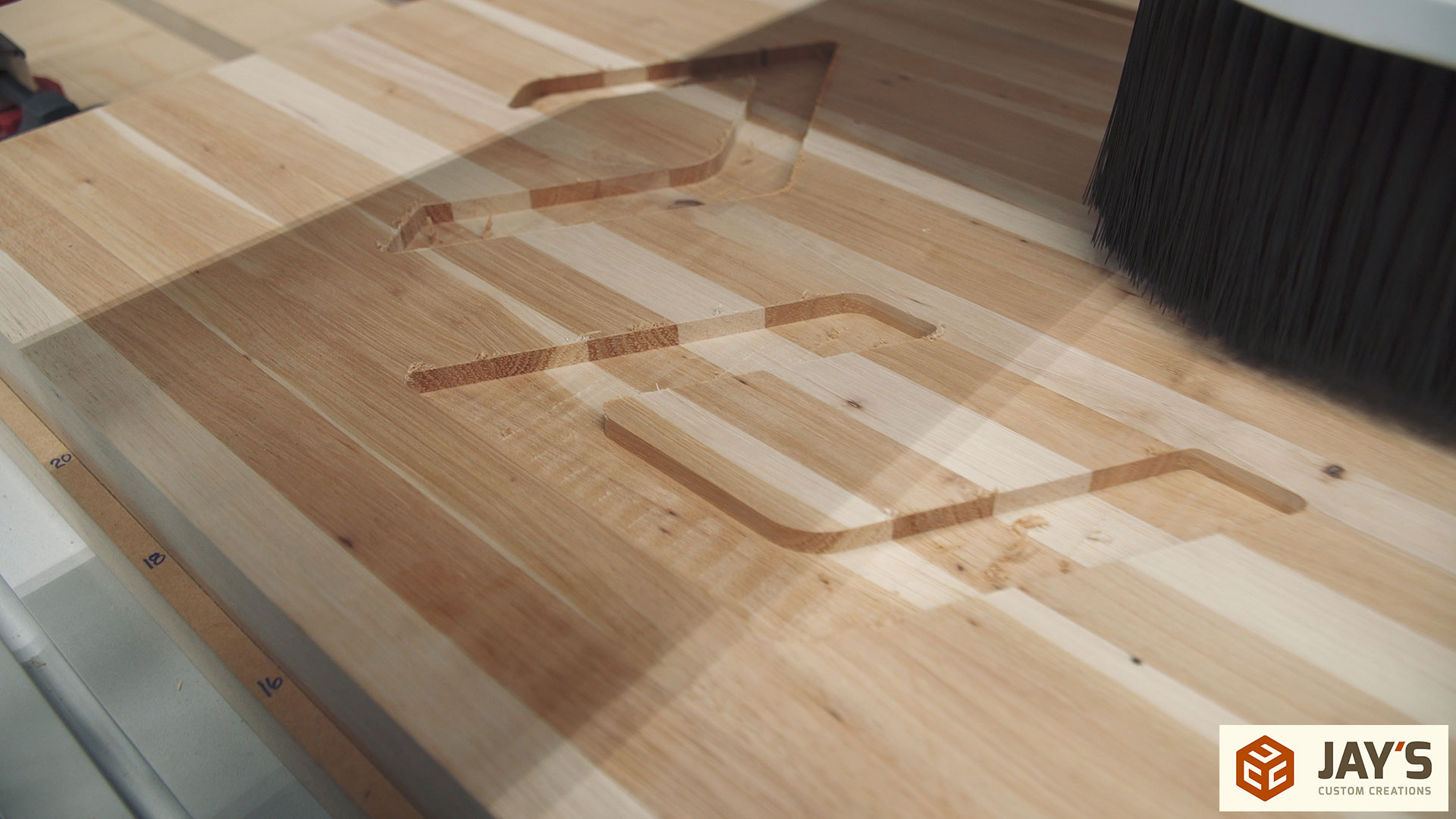
Followed by the V bit to establish the V perimeter. I removed the dust boot for video clarity at this point.
With the board flipped so the good side is up the juice groove is cut with a .5” round nose bit.
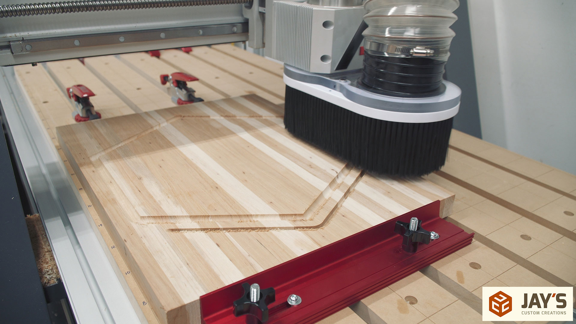
And the perimeter is established via two passes with a .25” end mill. I could have gone full depth here but I knew I would have to use a flush trim bit in the router to get rid of the tabs and any fuzz on bottom so why not just use the same process to trim the entire board.
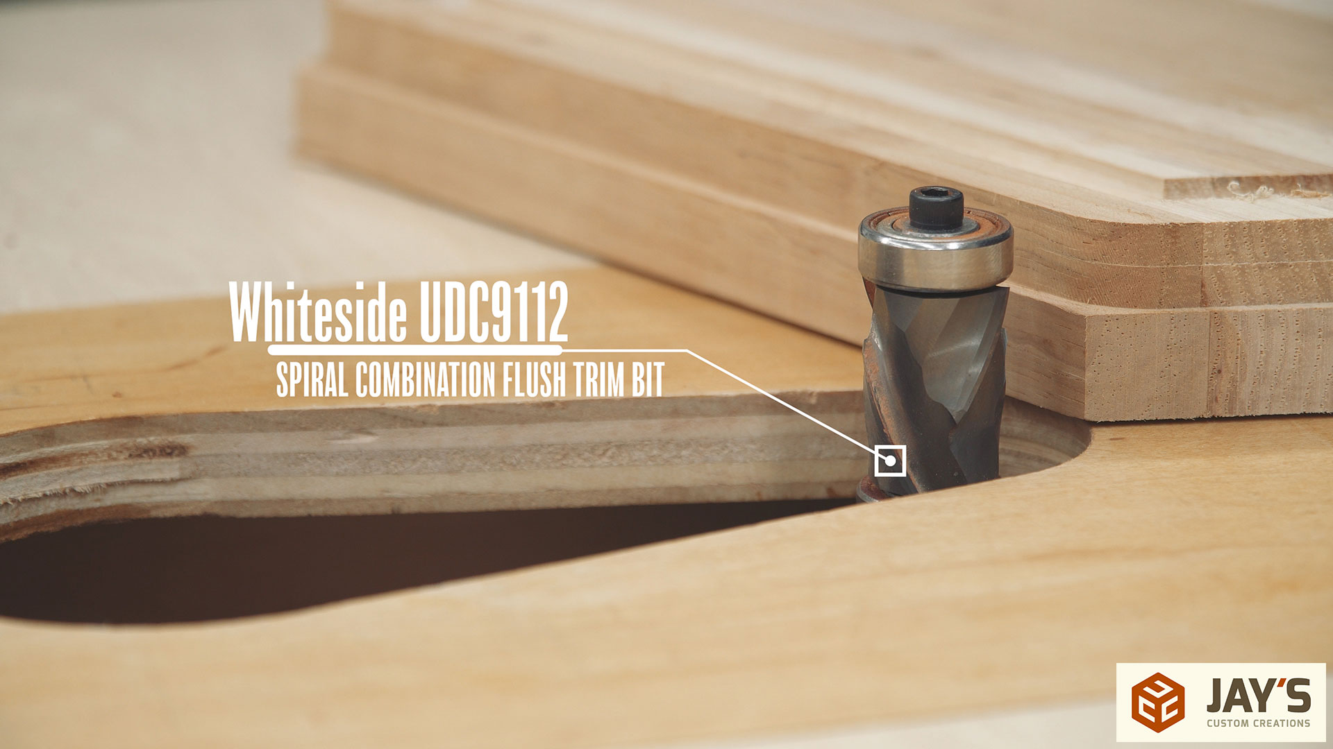
A couple quick cuts at the bandsaw will free the board.

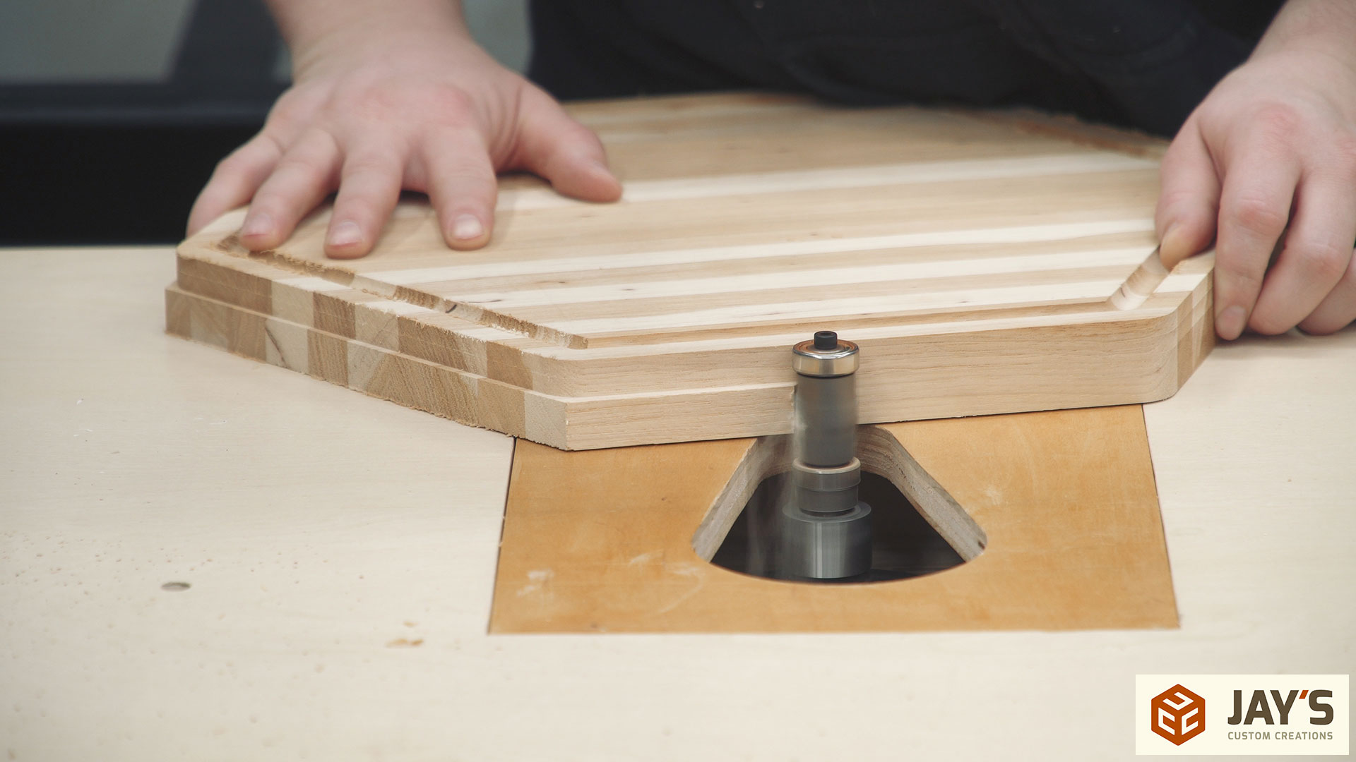
And a huge combination flush trim bit removes the rest of the waste with ease.
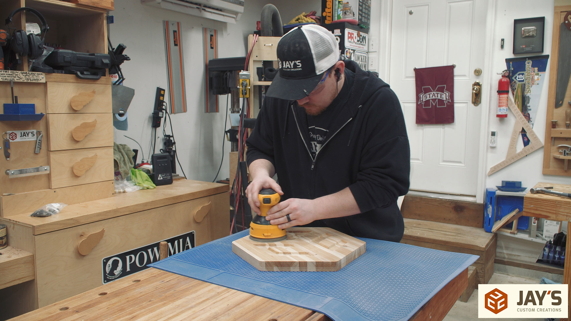
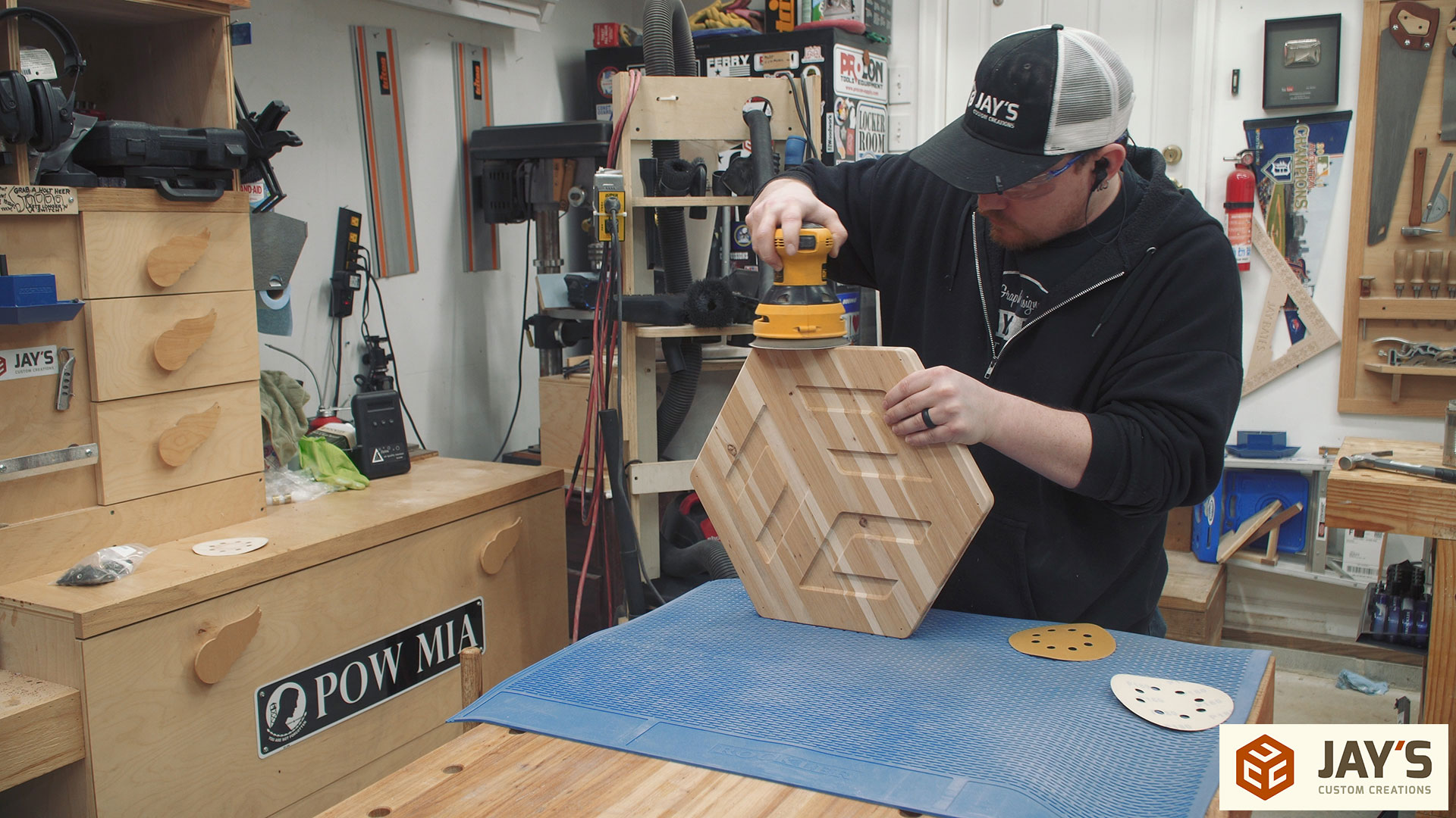
The drum sander is used to remove any little fuzz left on the surface from the CNC. Very few tools have a huge impact on time savings in the shop. A drum sander has proven to be one of them. Such a huge reduction in sanding time since getting this. More on this sander in a future tool talk post most likely.
Because I used an aggressive pocket path some touch up hand sanding is necessary. I had a 80% step over with this path. It would have left a finished surface if the step over was set around 25% but would also take three times longer to cut the path. Each situation is different and for this I figured it would be easier to cut faster on the CNC and spend a minute or two hand sanding. 6 one way, half a dozen the other way.
The drum sander has 80 grit installed so a fast cleanup pass of 180 grit with a random orbit sander is needed on the surface. At this point there are no problem areas with the surface so I’m literally only trying to remove the scratch marks from the drum sander. Super quick process.
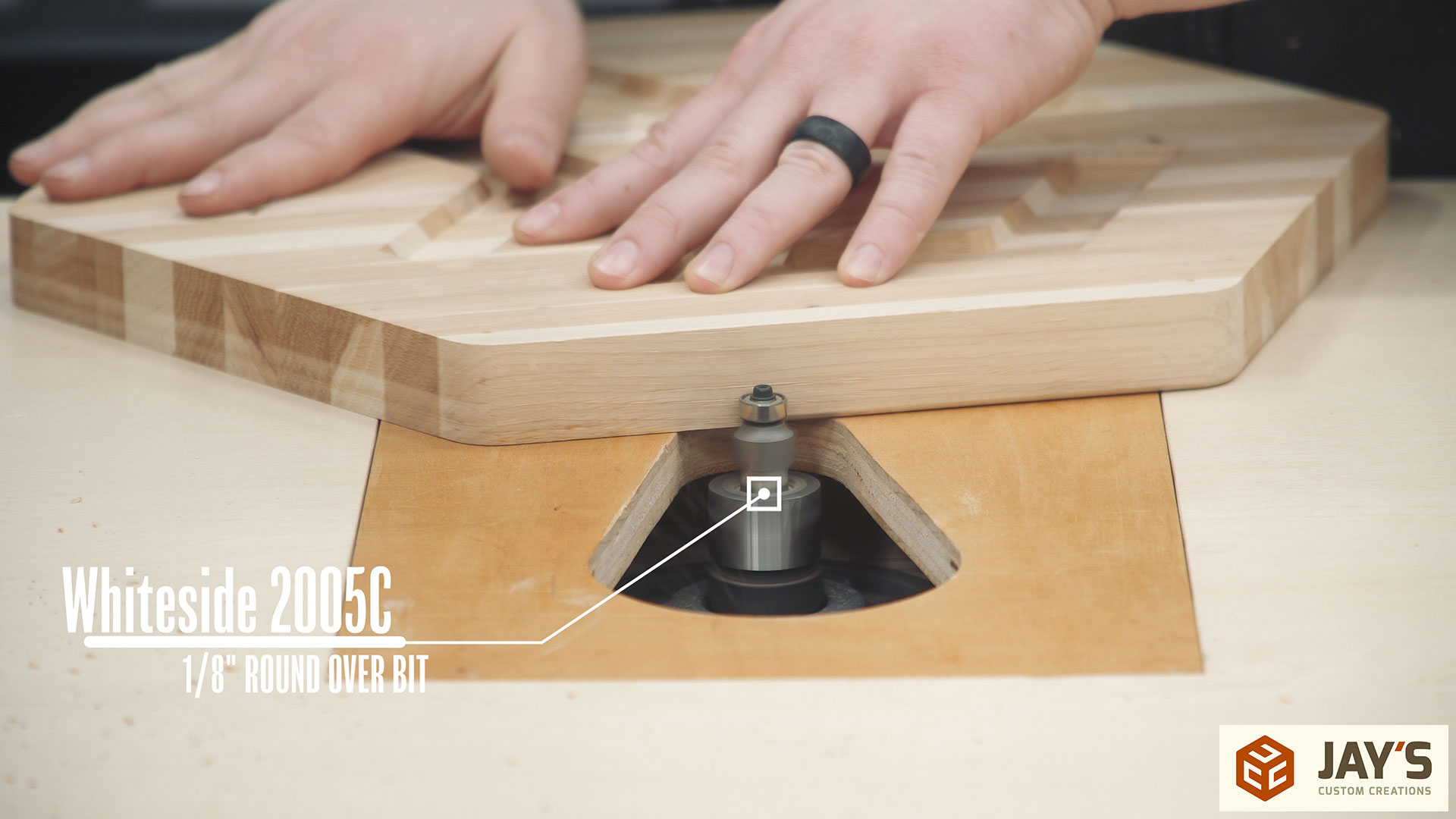
A .125” round over leaves a nice, clean, consistent edge that looks a lot more professional than a hand sanded edge. And the smaller radius keeps the bulky look of the board compared to a .25” or a .5” radius.
The end grain faces always need a bit more sanding than long grain faces.
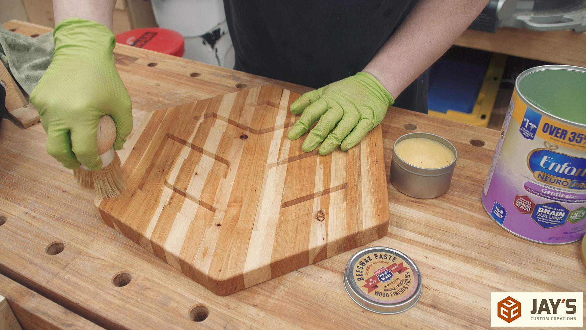
Mineral oil has always been my choice of finish for a cutting board. It’s incredibly cheap and readily available. The bottle I used here was $1.98 and it took one half used bottle plus the first third of this bottle for all 16 boards I made. Oiling a cutting board can get messy though. I use a dedicated piece of MDF as a work surface when finishing these boards. If making a bunch of cutting boards a better idea might be to get a plastic tote and dip the boards into a gallon or two of mineral oil and then let them drip. I don’t make enough cutting boards to justify storing a tote for that reason.

After letting the board soak for an hour or so and wiping down any excess I brush on a coat of beeswax paste to give a little more protection and really make the board feel smooth for its new owner.
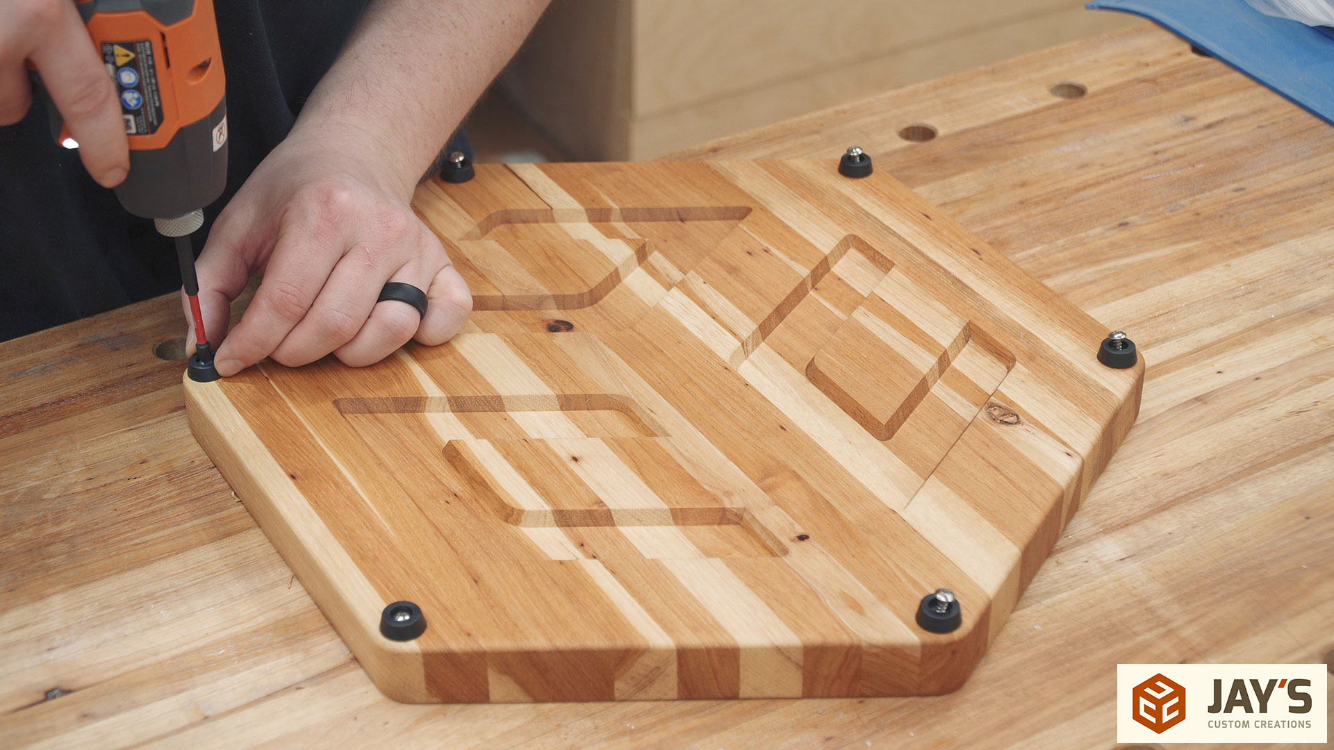
Finally the feet screw holes can be drilled.

And the feet are added. This is my first 6-feet cutting board. I know someone will ask so here is a link to the feet I used: https://amzn.to/2UQPNYw
The board turned out good. I gave this one away at a woodworking meetup in Birmingham, Alabama, on December 8. I don’t recall who won it as I was in the back of the room when the winner was drawn.


Leftovers are for quitters!
Excellent video as always. I really appreciate the detail in your explanations. Thanks, Jay!
Go Bears!
“Take it easy, take your time, but go, go.”